Low-temperature ethylene storage tank and condensate treatment method thereof
A low-temperature ethylene, treatment method technology, applied in the direction of fluid treatment, container filling method, container discharge method, etc., can solve the problems of safety hazards, damage to concrete structures, etc., and achieve the effect of improving efficiency
- Summary
- Abstract
- Description
- Claims
- Application Information
AI Technical Summary
Benefits of technology
Problems solved by technology
Method used
Image

Examples
Embodiment 1
[0047] In this embodiment, a low-temperature ethylene storage tank is provided, including:
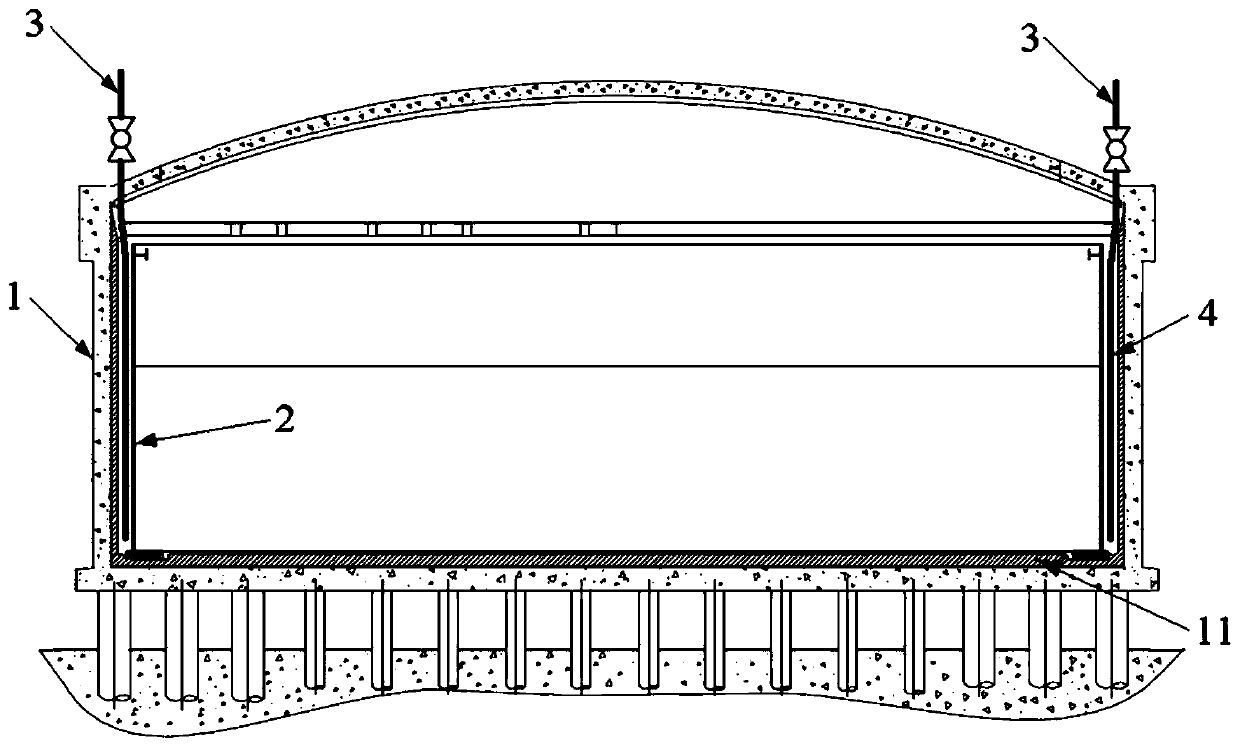
[0048] The outer tank 1 is a cylindrical reinforced concrete structure including a spherical tank top, and a first cold insulation material 11 is laid on the inner side of the bottom;
[0049] The inner tank 2 is made of Ni9 steel and is located inside the outer tank, and the top is provided with a ceiling plate;
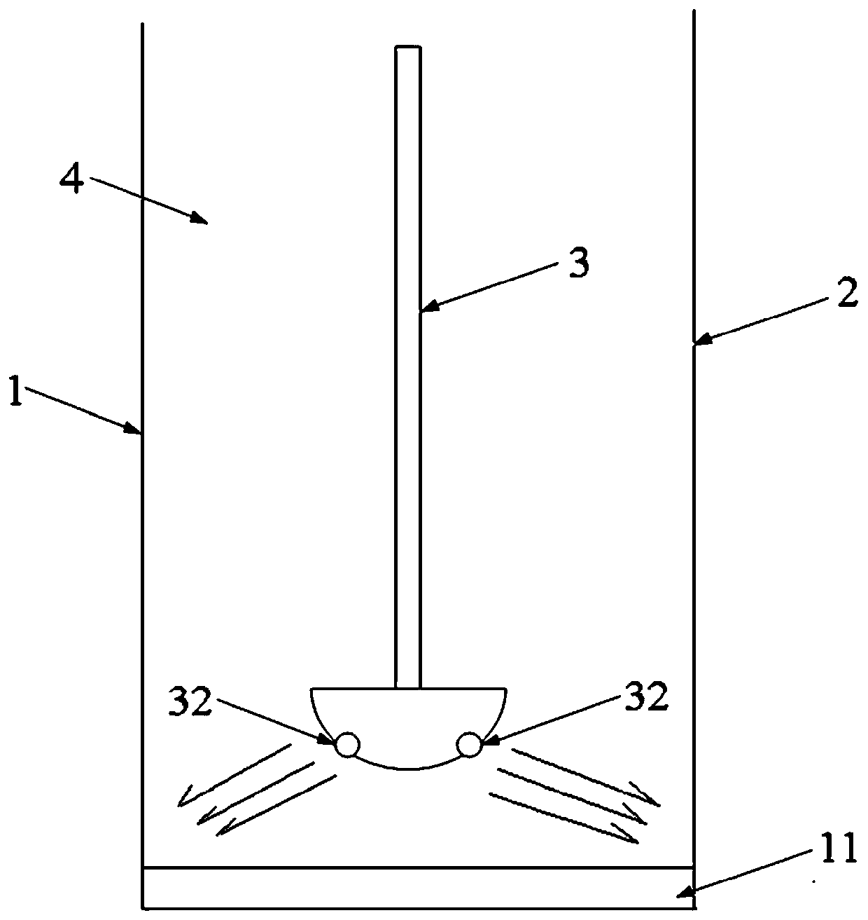
[0050] The inner wall of the outer tank 1 and the outer wall of the inner tank 2 are spaced apart to form an annulus 4 filled with a second cold insulation material 21; The top protrudes into the annulus space 4, and the gas outlet 32 of the nitrogen gas inlet pipe 3 is arranged near the bottom of the annulus space.
[0051] In this embodiment, unlike the nitrogen replacement system used for purging and drying, the low-temperature ethylene storage tank provided by the present invention introduces the nitrogen gas inlet pipe from the outer tank and sets it deep into the annul
Embodiment 2
[0062] The difference between this embodiment and embodiment 1 is:
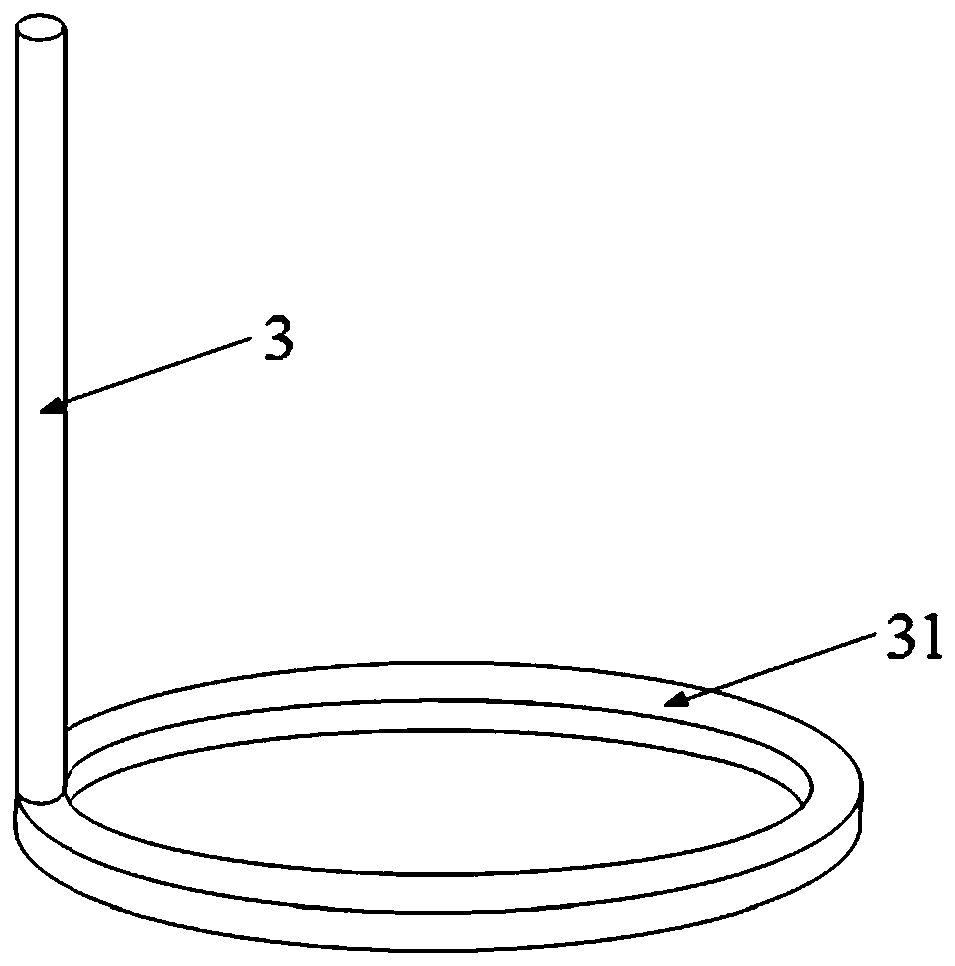
[0063] In this example, if image 3 with 4 As shown, the nitrogen inlet pipe 3 extends along the outer periphery of the inner tank 2 at the bottom of the annulus space 4 to form an annular inlet pipe 31, and the annular inlet pipe 31 is provided with several air outlets 32; the annular inlet pipe 31 is provided with There are two air outlets 32 facing differently.
[0064] In this embodiment, the volume of the ethylene storage tank is relatively large, so the distance between the bottom of the annular space formed by the outer tank and the inner tank in the circumferential direction of the inner tank is relatively long. After the top of the outer tank extends to the bottom of the annulus space, it extends along the outer periphery of the inner tank to form an annular inlet pipe with several gas outlets, so that nitrogen can purge any position in the circumferential direction of the annulus space.
[0065] In
Embodiment 3
[0068] In this embodiment, a method for treating condensate in a low-temperature ethylene storage tank as described in Embodiment 1 or 2 is provided, and the pressure and flow rate of nitrogen gas fed into the annulus space of the ethylene storage tank are controlled so that the nitrogen gas accumulated in the annulus The liquid ethylene in the space vaporizes.
[0069] In this embodiment, the treatment method also includes real-time monitoring of the dew point temperature of the annulus space, and when the dew point temperature of the annulus space reaches -45 to -50°C, stop feeding nitrogen; preferably, the treatment method simultaneously Monitor the concentration of gaseous ethylene in the annulus space, and stop feeding nitrogen when the dew point temperature of the annulus reaches -45~-50°C and the drop of gaseous ethylene concentration is not more than 0.5%. More preferably, stop feeding nitrogen , the concentration of gaseous ethylene is greater than 99.0%; most preferably
PUM
 Abstract
Description
Claims
Application Information
 - R&D Engineer
- R&D Manager
- IP Professional
- Industry Leading Data Capabilities
- Powerful AI technology
- Patent DNA Extraction
Browse by: Latest US Patents, China's latest patents, Technical Efficacy Thesaurus, Application Domain, Technology Topic.
© 2024 PatSnap. All rights reserved.Legal|Privacy policy|Modern Slavery Act Transparency Statement|Sitemap