Micromirror integrated with linear angle sensor

An angle sensor and micromirror technology, which is applied in the direction of instruments, optical components, optics, etc., can solve the problems of inability to apply high frequency and low frequency at the same time, complex angle measurement scheme system, poor process compatibility, etc., and achieve compact structure and low power consumption , The effect of high manufacturing efficiency

Active Publication Date: 2020-05-29
XIAN CHISHINE OPTOELECTRONICS TECH CO LTD
View PDF7 Cites 2 Cited by
  • Summary
  • Abstract
  • Description
  • Claims
  • Application Information

AI Technical Summary

Benefits of technology

This patented device includes an angular sensing unit made up of tiny mirrors arranged on a circle or rectangular lattice pattern. These reflective elements are designed into specific shapes for efficient reflection of light waves when they rotate around their center point. By integrating these components together, this design allows for precise measurement angles while minimized energy usage compared to traditional methods like optical interference techniques. Additionally, by feeding back signals from the sensor's surface onto its driving circuitry, it simplifies the overall operation of the device. Overall, this new type of element called Microscope (microscopes) provides improved performance over existing devices due to reduced complexity and lower costs.

Problems solved by technology

Technological Problem addressed by this patented technical problem relates to improving the efficiency or precision of current methods of measuring angles during MEMS mirror devices. Current solutions require expensive equipment like multiple component systems, including precise mountings, external force sources, etc., making them challenged from being able to accurately detect angular values even when they occur within limited range.

Method used


Image

  • Micromirror integrated with linear angle sensor
  • Micromirror integrated with linear angle sensor
  • Micromirror integrated with linear angle sensor

Examples


Embodiment 1

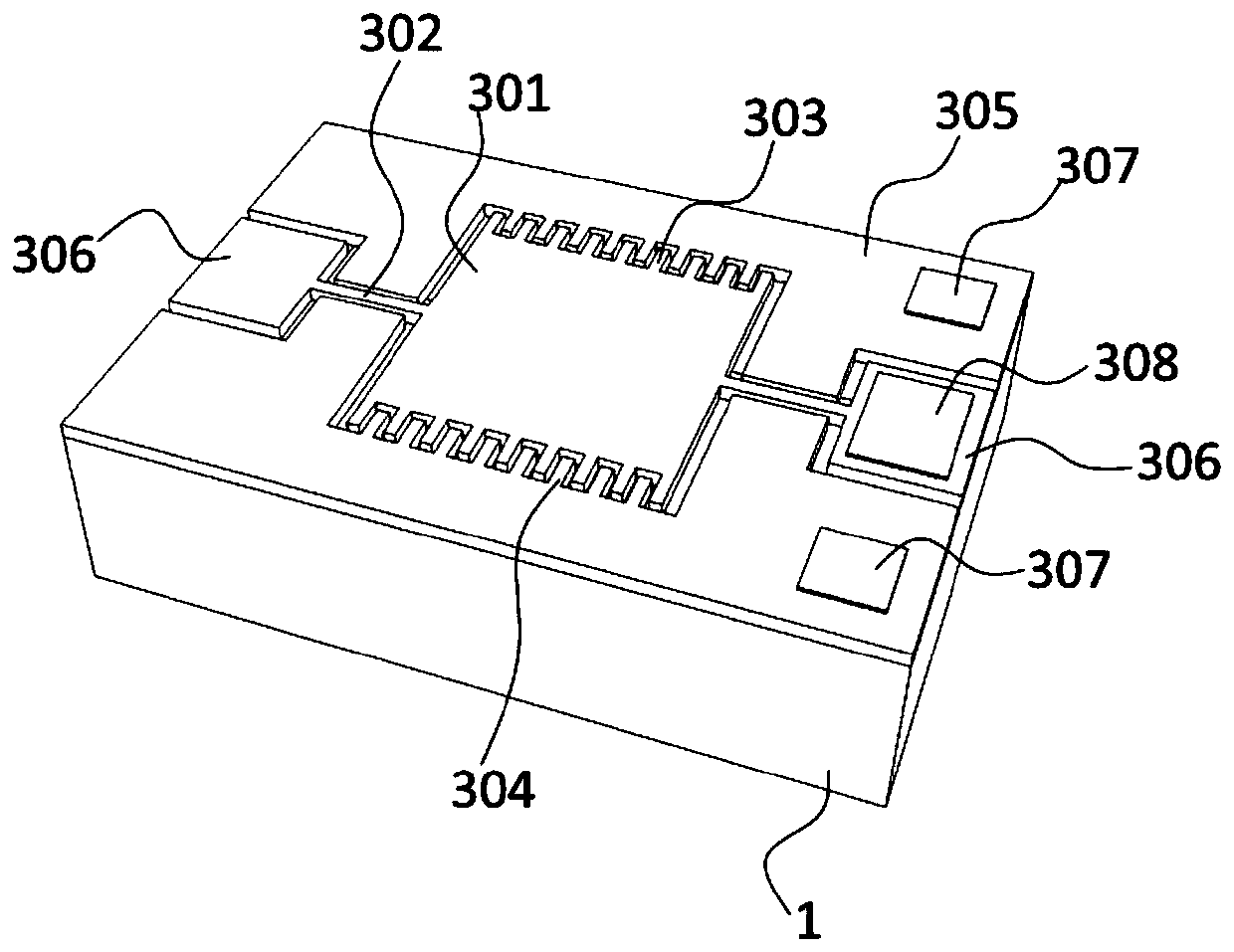
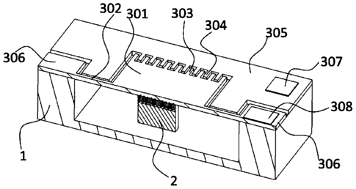
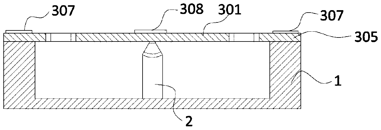
[0036] The micromirror of integrated linear angle sensor described in this embodiment, see Figure 1-7, including a base 1, an angle sensor 2, and a mirror element 3, the base 1 is a groove-like structure formed around the bottom surrounded by a frame, the mirror element 3 is a planar structure, the base 1 and the mirror The elements 3 are connected to form a box body with a hollow structure, and the angle sensor 2 is axially arranged in the hollow structure of the box body. The angle sensor 2 includes a stator 201 and a rotor 202 , and the rotor 202 is arranged on the upper part of the stator 201 . The lower end surface of the stator 201 is fixedly connected to the bottom of the groove-shaped structure of the base 1 , and the upper end surface of the rotor 202 is fixedly connected to the lower surface of the mirror element 3 . Both the stator 201 and the rotor 202 of the angle sensor 2 have fan-shaped array electrodes; the fan-shaped array electrodes of the stator 201 and the f

Embodiment 2

[0039] The micromirror of the integrated linear angle sensor described in this embodiment includes a base 1, an angle sensor 2, and a reflector element 3. The base 1 is a groove-like structure formed around the bottom surrounded by a frame, and the reflector element 3 It is a planar structure, the base 1 is connected with the reflector element 3 to form a box with a hollow structure, and an angle sensor 2 is axially arranged in the hollow structure of the box.

Embodiment 3

[0041] The micromirror of the integrated linear angle sensor described in this embodiment includes a base 1, an angle sensor 2, and a reflector element 3. The base 1 is a groove-like structure formed around the bottom surrounded by a frame, and the reflector element 3 It is a planar structure, the base 1 is connected with the reflector element 3 to form a box with a hollow structure, and an angle sensor 2 is axially arranged in the hollow structure of the box. The angle sensor 2 includes a stator 201 and a rotor 202 , and the rotor 202 is arranged on the upper part of the stator 201 . The lower end surface of the stator 201 is fixedly connected to the bottom of the groove-shaped structure of the base 1 , and the upper end surface of the rotor 202 is fixedly connected to the lower surface of the mirror element 3 . Both the stator 201 and the rotor 202 of the angle sensor 2 have fan-shaped array electrodes; the fan-shaped array electrodes of the stator 201 and the fan-shaped array


PUM


Abstract

The invention relates to the technical field of micro-nano optical devices, in particular to a micromirror integrated with a linear angle sensor. The micromirror comprises a base, an angle sensor anda reflector element. The base is of a groove-shaped structure formed by surrounding the bottom with a peripheral frame, the reflector element is of a plane structure, the base and the reflector element are connected to form a box body with a hollow structure, and the angle sensor is axially arranged in the hollow structure of the box body. The micromirror is integrated with the linear angle sensor, the rotation angle of the micromirror can be detected in real time, the output of the angle sensor and the rotation angle of the micromirror are in a linear relationship, the signal-to-noise ratio of the angle sensor is high, and the control precision of the micromirror is improved; and low-frequency and high-frequency scanning requirements are met.

Description


Claims


Application Information

Patent Timeline
Owner XIAN CHISHINE OPTOELECTRONICS TECH CO LTD
Why Eureka
Try Eureka