Lithium battery core with conductive electrode lugs

A lithium battery and tab technology, applied in the field of lithium battery cells, can solve problems such as non-conduction of metal layers, and achieve the effects of avoiding virtual welding, reducing production costs, and increasing the number of

Active Publication Date: 2020-08-07
HEFEI GUOXUAN HIGH TECH POWER ENERGY
View PDF6 Cites 2 Cited by
  • Summary
  • Abstract
  • Description
  • Claims
  • Application Information

AI Technical Summary

Benefits of technology

This new design allows for better electrical connections between cells without adding extra parts or increasing their size. It also improves efficiency when charging/discharging at very fast speeds while maintains good contact quality. Overall, this technology helps improve performance and cost reduction over existing methods.

Problems solved by technology

The problem addressed in this patented technology relates to increasing both the power capacity (energy) per unit weight or volume for Lithium ion batteries while also ensuring they operate safely under harsh conditions such as high temperatures without losing their effectiveness due to overheated cells caused by excessive heat generated during charging cycles.

Method used


Image

  • Lithium battery core with conductive electrode lugs
  • Lithium battery core with conductive electrode lugs
  • Lithium battery core with conductive electrode lugs

Examples


Embodiment 1

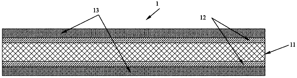
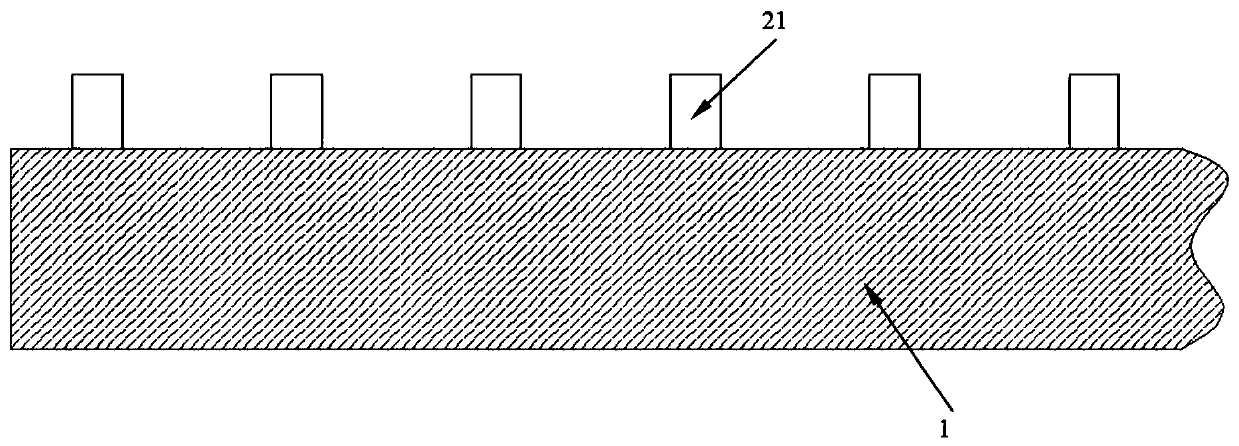
[0047] see Figure 1-7 , Figure 10 , Figure 24 , in an embodiment of the present invention, a lithium battery cell with tabs turned on includes a pole piece 1, the pole piece 1 includes a positive pole piece and a negative pole piece, and the positive pole piece and the negative pole piece are wound to form a battery cell 4, A diaphragm is arranged between the positive pole piece and the negative pole piece, and the lug bundles 23 on the positive pole piece and the negative pole piece are located at both ends of the battery core 4 respectively. The pole piece metal layer 12, the side of the pole piece metal layer 12 away from the pole piece insulating layer 11 is provided with an active material layer 13; the side of the pole piece 1 is provided with a tab part 2, and the tab part 2 includes at least one pole piece 1 fixedly connected tab bundle 23, the tab bundle 23 includes at least one tab piece 21, the tab piece 21 includes a tab insulating layer 22 and tab metal layers 2

Embodiment 2

[0050] see Figure 8-10 , Figure 24 , In this embodiment, three pole lug beams 23 are provided on one side of the pole piece 1, and the rest of the structures are the same as those in Embodiment 1.

Embodiment 3

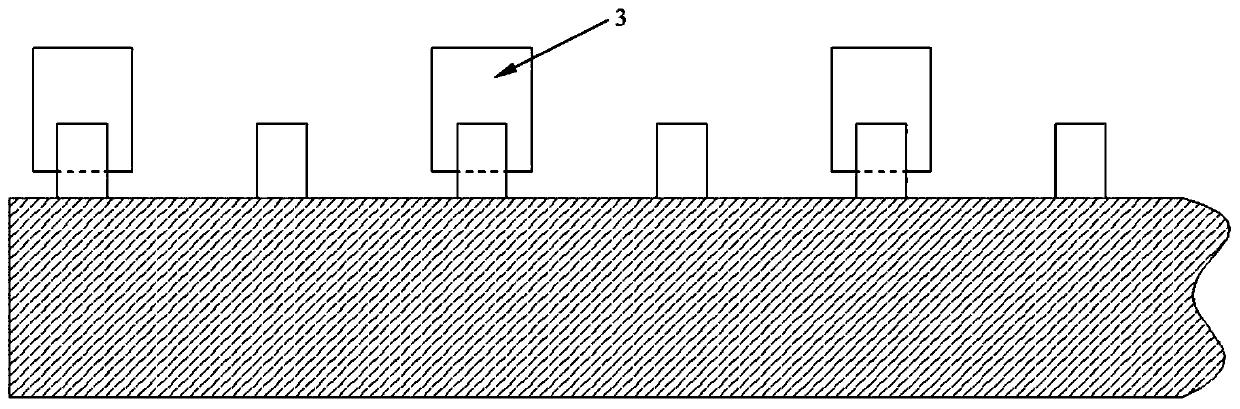
[0052] see Figure 11-15 , Figure 22-24 , in this embodiment, the projection of any tab piece 21 in the tab bundle 23 on the plane where the cell 4 is located does not overlap with the projections of all other tab pieces 21, and the tab bundle 23 is wrapped with conductive foil material 3, the tab bundle 23 includes a plurality of concentrically arranged tab pieces 21, and the tab piece 21 is provided with an adjacently arranged Nth tab piece 25 and an N+1th tab piece 26, and the Nth tab piece The end of the piece 25 away from the pole piece 1 is wrapped inside the N+1th tab piece 26, where N≥1, that is, in this embodiment, the tab piece 21 is a hollow structure in the middle, and the tab piece 21 is a rectangular structure, The hollowed out part has a rectangular structure, and the tab piece 21 at the center is not hollowed out, so after the pole piece 1 is wound, the hollowed out tab pieces 21 are nested in sequence to form a rectangular tab bundle 23, and then The tab bundl


PUM


Abstract

The invention discloses a lithium battery core with conductive electrode lugs. The lithium battery core comprises an electrode sheet, wherein an electrode lug part is arranged on one side of the electrode sheet, the electrode sheet comprises an electrode sheet insulating layer and electrode sheet metal layers located on the two sides of the electrode sheet insulating layer, an active substance layer is arranged on the side, away from the electrode sheet insulating layer, of each electrode sheet metal layer, the electrode lug part comprises at least one electrode lug bundle fixedly connected with the electrode sheet, the electrode lug bundle comprises at least one electrode lug sheet, the electrode lug sheet comprises an electrode lug insulating layer and electrode lug metal layers arrangedon the two sides of the electrode lug insulating layer, the electrode lug insulating layer is fixedly connected with the electrode sheet insulating layer, the electrode lug metal layer is fixedly connected with the electrode sheet metal layer, and the electrode lug sheets in the electrode lug bundle are conducted through a conductive foil material. According to the battery core structure disclosed by the invention, the conductive connection of the electrode lugs is realized in a manner of welding a conductive foil material on the electrode lugs, so that compared with a traditional manner, theuse amount of the foils can be greatly reduced, the production cost is reduced, and the energy density of the battery is remarkably improved.

Description


Claims


Application Information

Patent Timeline
Owner HEFEI GUOXUAN HIGH TECH POWER ENERGY
Why Eureka
Try Eureka