Airtightness detection device and airtightness detection method

A technology of air tightness detection and jacking device, which is applied in the direction of using liquid/vacuum degree for liquid tightness measurement and measuring the acceleration and deceleration rate of fluid, etc., which can solve the problem of insufficient sealing performance, water leakage, and damage to the battery system. And other issues

Pending Publication Date: 2021-01-29
SUZHOU JEE INTELLIGENT EQUIP CO LTD
View PDF0 Cites 5 Cited by
  • Summary
  • Abstract
  • Description
  • Claims
  • Application Information

AI Technical Summary

Benefits of technology

The technology described by this inventor has several benefits that can be explained through its unique design.

Problems solved by technology

The technical problem addressed by this patented technology relates to ensuring proper seal between two parts when creating batteries with specific areas where they require high-quality security measures such as gasoline tank caps on top. This requires tests conducted during assembly processes before final product shipment.

Method used


Image

  • Airtightness detection device and airtightness detection method
  • Airtightness detection device and airtightness detection method
  • Airtightness detection device and airtightness detection method

Examples


Embodiment Construction

[0057]The purpose, advantages and characteristics of the present invention will be illustrated and explained through the following non-limiting description of preferred embodiments. These embodiments are only typical examples of applying the technical solutions of the present invention, and any technical solutions formed by equivalent substitutions or equivalent transformations fall within the scope of protection of the present invention.

[0058]In the description of the scheme, it should be noted that the terms "center", "upper", "lower", "left", "right", "front", "rear", "vertical", "horizontal", " The orientation or positional relationship indicated by "inner" and "outer" is based on the orientation or positional relationship shown in the drawings, and is only for the convenience of description and simplified description, and does not indicate or imply that the device or element referred to must have a specific orientation , It is constructed and operated in a specific orientation, so


PUM


Abstract

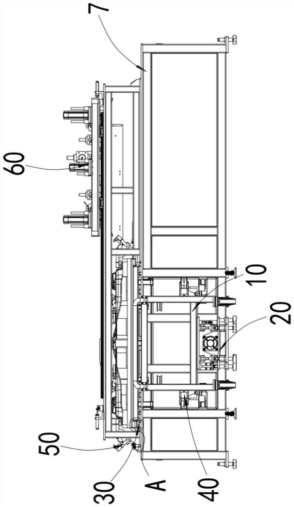
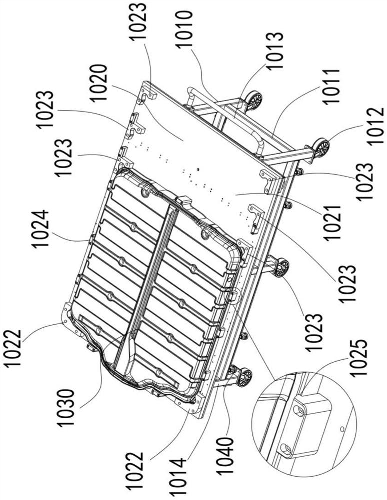
The invention discloses an air tightness detection device and an air tightness detection method. The air tightness detection device provides special equipment for detecting the air tightness of a battery pack PACK upper cover, a workpiece sealing mold is arranged to form a sealable cavity with the battery pack PACK upper cover, and the position precision of the workpiece sealing mold is ensured through a positioning structure. An edge sealing mechanism and an anti-deformation mechanism are combined to guarantee the sealing performance and prevent the battery pack PACK upper cover from deforming during detection, so that reliable conditions are created for airtightness detection, airtightness detection of the battery pack PACK upper cover can be effectively carried out, and a basic guarantee is provided for improving the airtightness of the battery pack.

Description


Claims


Application Information

Patent Timeline
Owner SUZHOU JEE INTELLIGENT EQUIP CO LTD
Why Eureka
Try Eureka