Quick design method for three-dimensional chemical milling template
A design method and template technology, applied in the direction of design optimization/simulation, special data processing application, geometric CAD, etc., can solve the problems of long development cycle of three-dimensional milling template, inability to meet the production requirements, and prone to quality problems, so as to shorten the time Development cycle, improve design quality, rapid design effect
- Summary
- Abstract
- Description
- Claims
- Application Information
AI Technical Summary
Problems solved by technology
Method used
Image

Examples
Embodiment 1
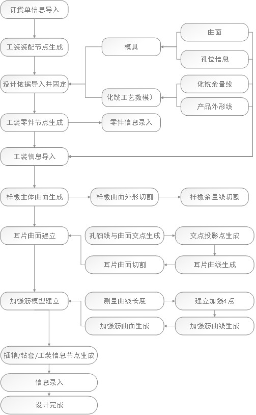
[0034] A three-dimensional milling template rapid design method, including structure tree generation, three-dimensional milling template modeling, three-dimensional milling template detection; said structure tree generation is used to generate assembly nodes, part nodes, standard parts nodes in CATIA, And input corresponding material, standard part information; Described three-dimensional milling sample model modeling includes model profile design, model lug design, model stiffener design that carry out successively, and described model ear piece design is based on the hole axis of mold hole and model plate The intersection point of the main surface is obtained by projecting the projection point on the edge of the main surface, and then the ear curve is generated, and the ear surface is cut to establish the ear surface.
[0035] The invention is a knowledge-based, normalized, standardized and parametric design method, which can effectively improve the design quality and prevent mi
Embodiment 2
[0037] This embodiment is optimized on the basis of Embodiment 1, using the mold hole to generate the hole axis A, using the mold film surface S to intersect the hole axis A in space to form a point B, and point B forms a point on the edge of the main curved surface of the projection model C; through the point command, point D and point F, which are 30-40mm away from point C, are formed on the edge line L of the main surface of the template; the edge line L of the main surface is cut through point D and point E to form a curve DE; the curve DE is on the mold film surface S is equidistantly translated by 40mm to form a curve FG; connect the 4 endpoints of the curve DE and curve FG to form a wireframe H; project the wireframe H onto the mold film surface S to form a new wireframe M; use the wireframe M to cut the mold The surface S of the film is obtained to obtain the surface of the ear piece of the three-dimensional milling model.
[0038] Other parts of this embodiment are the s
Embodiment 3
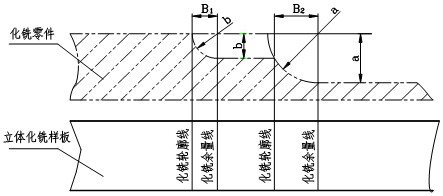
[0040] This embodiment is optimized on the basis of Embodiment 1 or 2. In the model surface design, according to the product outline, the mold surface is cut to obtain the model main surface; according to the chemical milling allowance line, the model main surface is Execute the chemical milling area.
[0041] Further, such as figure 2 As shown, the establishment formula of the chemical milling allowance line is as follows:
[0042] The formula for one-time chemical milling is:
[0043] B=c×b
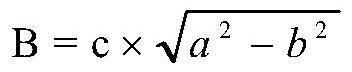
[0044] The calculation formula of secondary chemical milling is:
[0045]
[0046] Among them, B is the width of chemical milling allowance;
[0047] c is the corrosion coefficient;
[0048] a is the depth of secondary chemical milling;
[0049] b is a chemical milling depth.
[0050] Other parts of this embodiment are the same as those of Embodiment 1 or 2 above, so details are not repeated here.
PUM
 Abstract
Description
Claims
Application Information
 - R&D Engineer
- R&D Manager
- IP Professional
- Industry Leading Data Capabilities
- Powerful AI technology
- Patent DNA Extraction
Browse by: Latest US Patents, China's latest patents, Technical Efficacy Thesaurus, Application Domain, Technology Topic.
© 2024 PatSnap. All rights reserved.Legal|Privacy policy|Modern Slavery Act Transparency Statement|Sitemap