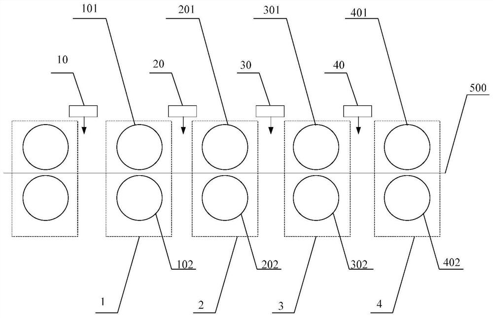
Rolling process of 2 mm corrosion-resistant hot-rolled coiled plate

A corrosion-resistant, coiling technology, applied in the direction of manufacturing tools, metal rolling, metal rolling, etc., can solve the problems affecting the progress of the cold rolling process, and achieve the effect of good flatness.

Active Publication Date: 2021-03-12
福建三宝特钢有限公司
View PDF6 Cites 1 Cited by
  • Summary
  • Abstract
  • Description
  • Claims
  • Application Information

AI Technical Summary

Benefits of technology

This technology allows for quicker and easier correction or compensation on both sides during production without affecting productivity. It uses different levels of precision when controlling the rotation speeds at two ends of each end of the final rolling stand compared to traditional methods like straightening. By changing the positions and dimensions of these components, the system becomes able to accurately correct any deviations from ideal conditions while still maintaining high efficiency.

Problems solved by technology

This patented technical problem addressed in this patents relates to improving the efficiency or effectiveness of producing thin plated products through thermal treatment techniques such as cool down processing steps before final shaping operations like forming them from cast ingots. Specifically, while maintaining quality control over these manufacturing stages, reducing cost and labor expenses associated with each stage' operation becomes important because doing so helps reduce operating costs and improve profitability.

Method used


Image

  • Rolling process of 2 mm corrosion-resistant hot-rolled coiled plate

Examples


Embodiment Construction

[0036] In order to make the objects and advantages of the present invention clearer, the present invention will be further described below in conjunction with the examples; it should be understood that the specific examples described here are only for explaining the present invention, and are not intended to limit the present invention.

[0037] Preferred embodiments of the present invention are described below with reference to the accompanying drawings. Those skilled in the art should understand that these embodiments are only used to explain the technical principle of the present invention, and are not intended to limit the protection scope of the present invention.

[0038] It should be noted that, in the description of the present invention, terms such as "upper", "lower", "left", "right", "inner", "outer" and other indicated directions or positional relationships are based on the terms shown in the accompanying drawings. The direction or positional relationship shown is onl


PUM


Abstract

The invention relates to a rolling process of a 2 mm corrosion-resistant hot-rolled coiled plate. The rolling process comprises the following steps: detecting the flatness of a first position, a second position, a third position and a fourth position of a metal plate by utilizing a flatness detector to generate a real-time flatness matrix P (P1, P2, P3, P4), wherein the first position is arrangedbetween a first finishing mill and a second finishing mill, the second position is arranged between the second finishing mill and a third finishing mill, the third position is arranged between the third finishing mill and a fourth finishing mill, and the fourth position is arranged between the fourth finishing mill and a fifth finishing mill; and according to changes of the first real-time flatness and the second real-time flatness, adjusting the roller rotating speed and the rotating speed difference of the fourth finishing mill and the fifth finishing mill. The follow-up rotating speed and rotating speed difference of the fourth finishing mill and the fifth finishing mill are adjusted according to the changes of the flatness of the first position and the second position, the metal plateswith the flatness not meeting the requirement are corrected in time, real-time feedback is conducted, and accurate adjustment of the flatness of the metal plates is achieved.

Description


Claims


Application Information

Patent Timeline
Owner 福建三宝特钢有限公司
Why Eureka
Try Eureka