Mold and manufacturing process thereof

A mold and process technology, applied in the field of mold and its manufacturing process, can solve problems that are not conducive to improving product timeliness and cost competitiveness, cost reduction, and lengthened development cycle, so as to improve mold forming efficiency, facilitate cooling and solidification, and prevent The effect of the leak

Active Publication Date: 2021-03-26
中国机械总院集团江苏分院有限公司
View PDF5 Cites 0 Cited by
  • Summary
  • Abstract
  • Description
  • Claims
  • Application Information

AI Technical Summary

Problems solved by technology

It is mainly used in mass production. Although the production and manufacturing costs of molds are relatively high, due to mass production, the cost of each product is greatly reduced.
In the trial production of automobile products, molds are widely used. The objects of trial production of automobile products mainly refer to prototype cars, body parts, body parts, interior and exterior trims and parts. Trial prototype cars generally include concept cars, verification cars and test cars. Conceptual design pays more attention to appearance and shape, while the design and trial production of verification vehicles and test vehicles emphasizes reasonable size and qualified quality. To a certain extent, the production efficiency of modules is delayed. As vehicle manufacturers launch new models with shorter and shorter cycles and quickly occupy the brand market, the use of existing molds makes the development cycle at this stage longer, which is not conducive to improving the timeliness of products. Sexuality and cost competitiveness, so a mold and its manufacturing process are proposed

Method used


Image

  • Mold and manufacturing process thereof
  • Mold and manufacturing process thereof
  • Mold and manufacturing process thereof

Examples


Embodiment

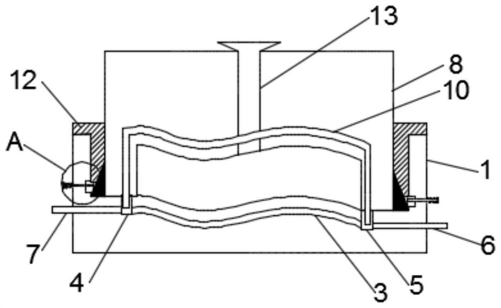
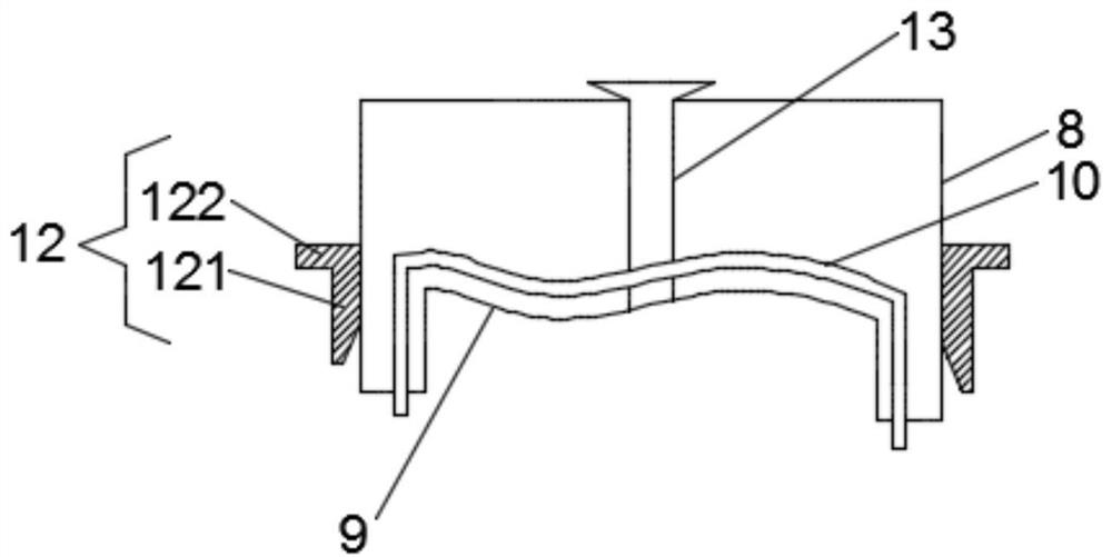
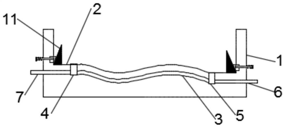
[0023] see Figure 1-3 :

[0024] Step 1: Prepare the lower mold base 1, set up the first processing groove 2 on the lower mold base 1, process the lower mold surface of the target blank film on the bottom wall of the first processing groove 2, and A peripheral side of the processing groove 2 is fixedly connected with a limit ring 11;

[0025] Step 2: pre-embed the lower mold base pipe 3 inside the lower mold base 1 and at the lower side of the first processing tank 2, the lower mold base pipeline 3 is used for cooling medium to facilitate forming The module is cooled and solidified, and the two ends of the lower mold base pipe 3 are respectively connected with the A tee pipe 4 and the B tee pipe 5, and at the free ends of the A tee pipe 4 and the B tee pipe 5 Connect the liquid outlet pipe 6 and the liquid inlet pipe 7 respectively, the free ends of the liquid outlet pipe 6 and the liquid inlet pipe 7 all pass through the side wall of the lower mold base 1, and the external...


PUM


Abstract

The invention relates to the technical field of molds, and particularly discloses a manufacturing process of a mold. A lower mold base pipeline is pre-buried in a position in the interior of a lower mold base and located on the lower side of a first machining groove, so that cooling and curing are conveniently carried out on a formed mold part, the two ends of the lower mold base pipeline are connected with a three-way pipeline A and a three-way pipeline B correspondingly, the free ends of the three-way pipeline A and the three-way pipeline B are respectively connected with a liquid outlet pipeline and a liquid inlet pipeline, the free ends of the liquid outlet pipeline and the liquid inlet pipeline penetrate out of the side wall of the lower mold base, and two free ends of an upper mold base pipeline are respectively clamped into joints of the three-way pipeline A and the three-way pipeline B along with buckling of an upper mold base and the lower mold base. After a forming medium ispoured into a pouring hole channel, a water inlet and a water outlet of an external cooling water circulation system are connected with the liquid outlet pipeline and the liquid inlet pipeline respectively, cooling water continuously and circularly flows around a mold cavity formed between the upper mold surface and the lower mold surface, the forming medium is cooled in an accelerated mode, and therefore the mold forming efficiency is effectively improved.

Description

technical field [0001] The invention relates to the technical field of mold technology, and the specific field is a mold and its manufacturing process. Background technique [0002] Rapid tooling is a tool that uses its specific shape to form products with a certain shape, size and surface accuracy. It is mainly used in mass production. Although the production and manufacturing costs of molds are relatively high, the cost of each product is greatly reduced due to mass production. In the trial production of automobile products, molds are widely used. The objects of trial production of automobile products mainly refer to prototype cars, body parts, body parts, interior and exterior trims and parts. Trial prototype cars generally include concept cars, verification cars and test cars. Conceptual design pays more attention to appearance and shape, while the design and trial production of verification vehicles and test vehicles emphasizes reasonable size and qualified quality. T...

Claims


Application Information

Patent Timeline
IPC IPC(8): B29C39/02B29C39/26B29C39/38B29C39/32B29L31/30
CPCB29C39/02B29C39/26B29C39/38B29C39/32B29L2031/3005Y02P90/30
Inventor 庄百亮周永松吴强徐先宜张彦美王金刚陈欣吕刘丁赫
Owner 中国机械总院集团江苏分院有限公司
Why Eureka
Try Eureka