Pressure vessel and vehicle

A technology for pressure vessels and bottle valves, which is applied to pressure vessels, road vehicles, vehicle parts, etc. It can solve the problems of pressure vessel A0 sealing failure and poor sealing reliability, so as to achieve reliable vehicle operation, strong sealing reliability, and reduce sealing difficulty Effect

Active Publication Date: 2021-03-26
FTXT ENERGY TECH CO LTD
View PDF9 Cites 1 Cited by
  • Summary
  • Abstract
  • Description
  • Claims
  • Application Information

AI Technical Summary

Problems solved by technology

[0003] In the existing pressure vessel A0, for example in the patent of publication number CN101548128B, such as Figure 4 As shown, the valve seat A1 is sleeved and sealed outside the bottle valve A2, and the liner A3 is sleeved and sealed outside the valve seat A1. In order to ensure the airtightness of the container, a second A sealing ring A5 ensures the tightness between the valve seat A1 and the bottle valve A2, and a second sealing ring A6 is set between the inner tank A3 and the valve seat A1 to ensure the tightness between the inner tank A3 and the valve seat A1. It is necessary to ensure two seals at the same time to realize the seal between the bottle valve A2 and the communication channel A4. When any one of the first seal ring A5 and the second seal ring A6 fails, it may cause the overall seal failure of the pressure vessel A0, so The scheme has poor sealing reliability

Method used


Image

  • Pressure vessel and vehicle
  • Pressure vessel and vehicle
  • Pressure vessel and vehicle

Examples


Example Embodiment

[0026] It should be noted that the features in the present invention in the present invention can be combined with each other in the case of an unable conflict.

[0027] The present invention will be described in detail below with reference to the drawings.

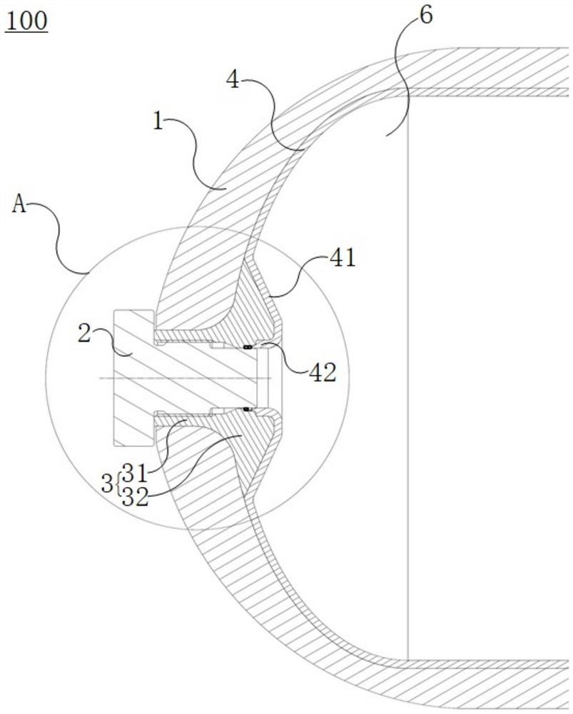
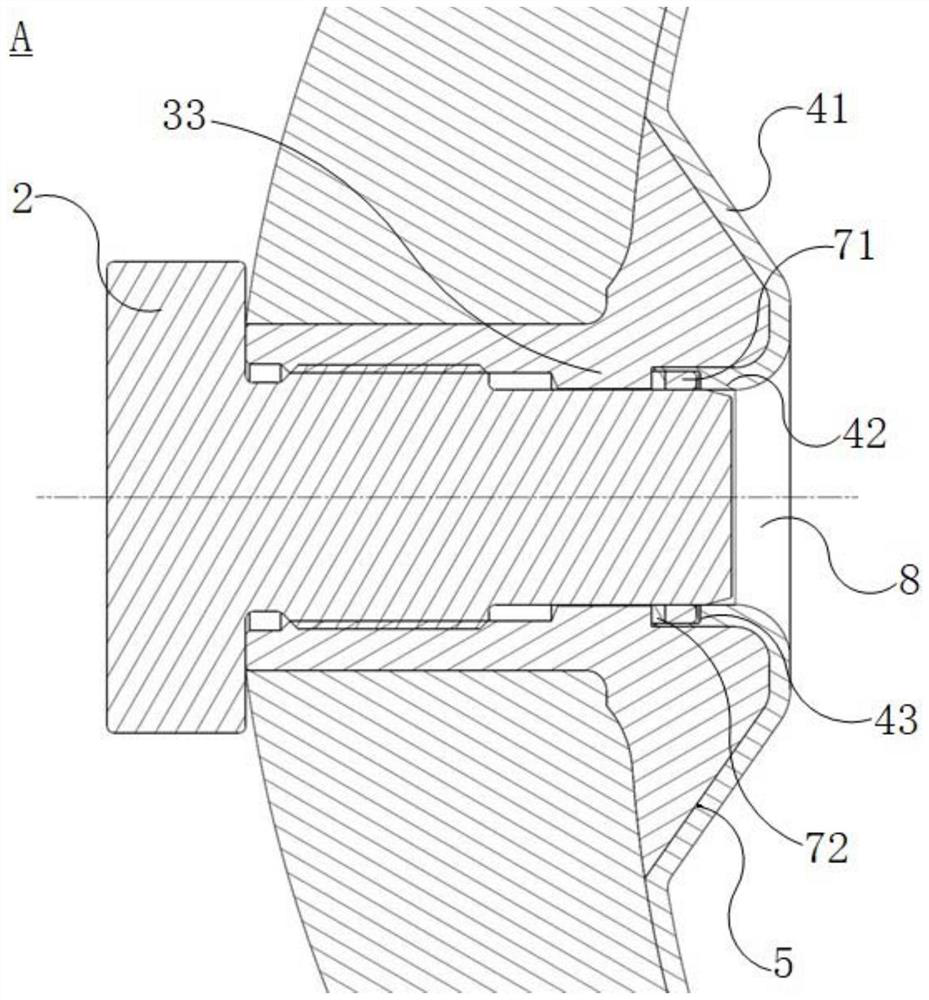
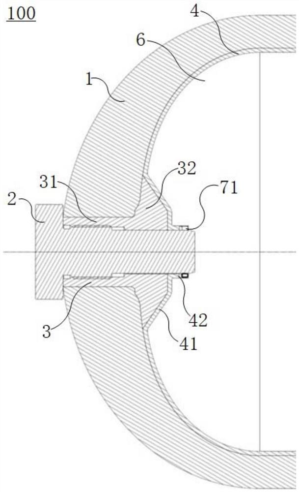
[0028] Below Figure 1 - Figure 3 The pressure vessel 100 of the embodiment of the present invention will be described with reference to the examples.

[0029] Such as Figure 1 - Figure 3 As shown, the pressure vessel 100 can include a housing 1, a bottle valve 2, a valve seat 3, a housing 4 having a storage space 6, a storage space 6 for storing a gas, a liquid, and the like. The housing 1 has a communication passage 8 that communicates with the outside, and the bottle valve 2 is provided at the communication passage 8 for adjusting the opening degree of the communication passage 8, and the bottle valve 2 is opened, and the external fluid can pass through the bottle valve 2 through communication. The passage 8 enters the press


PUM


Abstract

The invention discloses a pressure vessel and a vehicle. The pressure vessel comprises a shell, a cylinder valve, a valve seat and an inner container, a storage space is formed in the shell, the shellis provided with a communication channel enabling the storage space to communicate with the outside, the cylinder valve is arranged at the communication channel and used for adjusting the opening degree of the communication channel, at least part of the valve seat is supported at the position between the cylinder valve and the communication channel, the inner container is arranged on the inner wall face, facing the storage space, of the shell, an inner container connecting part is formed between the inner container and the shell, the cylinder valve penetrates out of the inner container, and the inner container is further provided with an attaching part suitable for being attached to the peripheral face of the cylinder valve in a surrounding mode. According to the pressure vessel, by arranging the inner container connecting part, sealing between the cylinder valve and the communicating channel can be achieved only by guaranteeing sealing between the inner container and the cylinder valve, and the sealing reliability between the cylinder valve and the communicating channel is high.

Description


Claims


Application Information

Patent Timeline
Owner FTXT ENERGY TECH CO LTD
Why Eureka
Try Eureka