Steel bar scattering machine and steel bar feeding machine

A technology for breaking up machines and steel bars, which is applied to conveyors, conveyor objects, transportation and packaging, etc. It can solve the problems of requiring manual assistance, operation, labor and safety hazards, etc., and achieve a wide range of applications and universal use. The effect of strong performance and improving production efficiency

Inactive Publication Date: 2021-04-16
CHENGDU GUTE MACHIENRY WORKS
View PDF9 Cites 3 Cited by
  • Summary
  • Abstract
  • Description
  • Claims
  • Application Information

AI Technical Summary

Benefits of technology

This patented technology describes a system called a reactor used during manufacturing processes where high pressure water jet cutting (HPWC) machines are being developed due to their ability to cut thin metal pipes quickly without causing damage or requiring more maintenance than traditional methods like drilling holes with screws. These systems use multiple set of rotating chains made up of gears attached together at one point along its entire route between two rollers located underground. By controlling these chains' movement, it allows for precise placements of steel rods within specific areas of the pipe while also allowing for flexibility in selecting suitable treatment options based upon realistic needs. Overall this design improves productivity and reduces costs compared to current methods.

Problems solved by technology

This patented technical problem addressed by this patents relates to manually handling materials during different stages or locations within an industrial facility where multiple types of machinery may work together for various purposes like cutting metal rods into smaller pieces that can then be used again later when needed. Additionally, it also highlights how human error could lead to unsafe conditions if workers were working with these small parts while they worked around them themselves.

Method used


Image

  • Steel bar scattering machine and steel bar feeding machine
  • Steel bar scattering machine and steel bar feeding machine
  • Steel bar scattering machine and steel bar feeding machine

Examples


Embodiment 1

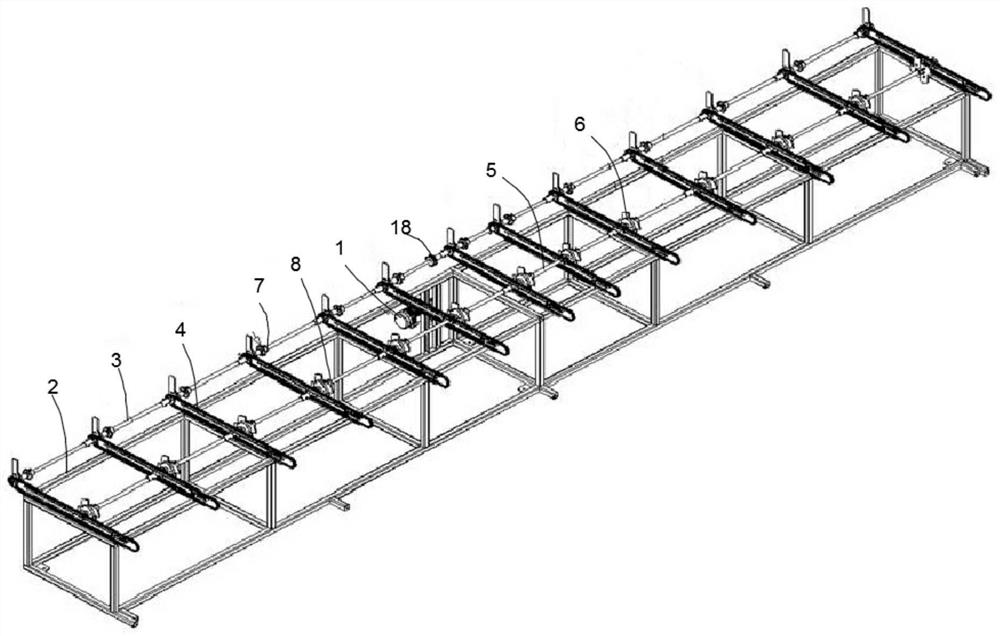
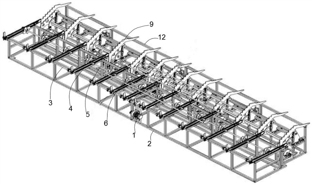
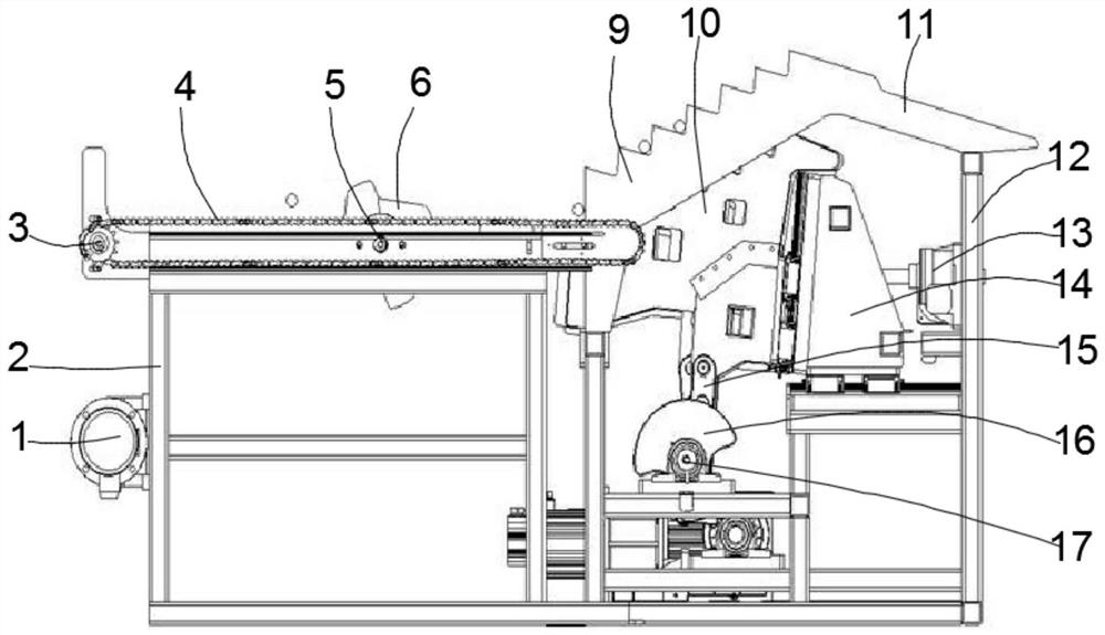
[0028] Such as Figure 1 to Figure 4 As shown, the steel bar breaking machine provided by this embodiment includes a frame 2, the top of the frame 2 is located in the same horizontal plane and is provided with multiple sets of sprocket chain transmission assemblies 4 in parallel, and the frame 2 is located on multiple sets of sprocket chains. The transmission feeding end of the transmission assembly 4 is provided with a sprocket transmission shaft 3, and the sprocket transmission shaft 3 is connected with a rotating drive mechanism; Wheel drive shaft 3 is fixedly connected with the same axis; The upper turret on the frame 2 within the transmission length range of sprocket chain drive assembly 4 is provided with a material transfer shaft 5 parallel to the sprocket drive shaft 3, and the material transfer shaft 5 is connected with Dial material driving mechanism, the material dial drive shaft 5 is coaxially fixed with a plurality of multi-tooth dial cam plates 6 .

[0029] In this

Embodiment 2

[0034] Such as figure 1 with Figure 4As shown, the steel bar feeding machine provided in this embodiment includes a steel bar breaking machine and a steel bar rubbing machine; the steel bar breaking machine includes a frame 2, and the top of the frame 2 is located in the same horizontal plane and is provided with multiple sets of sprockets in parallel Chain transmission assembly 4, the transmission feed end that is positioned at multiple groups of sprocket chain transmission assemblies 4 on frame 2 is provided with sprocket transmission shaft 3, and sprocket transmission shaft 3 is connected with rotary drive mechanism; The sprocket 7 is all sleeved on the sprocket drive shaft 3 and is coaxially fixedly connected with the sprocket drive shaft 3; Parallel material shifting transmission shaft 5 is connected with a material shifting drive mechanism, and a plurality of multi-tooth dialing cam plates 6 are coaxially fixed on the dialing transmission shaft 5 at intervals.

[0035] I


PUM


Abstract

The invention discloses a steel bar scattering machine and a steel bar feeding machine, and relates to the technical field of machine manufacturing. The steel bar scattering machine comprises a rack, a plurality of sets of chain wheel and chain transmission assemblies are erected on the rack, and a chain wheel transmission shaft is arranged on the rack and connected with a rotary driving mechanism; driving chain wheels of the multiple chain wheel and chain assemblies are arranged on the chain wheel transmission shaft in a sleeving manner and coaxially and fixedly connected with the chain wheel transmission shaft; and a material stirring transmission shaft is erected on the rack in a rotating manner, the material stirring transmission shaft is connected with a material stirring driving mechanism, and a plurality of material stirring cam plates are coaxially fixed to the material stirring transmission shaft at intervals. The steel bar feeding machine comprises the steel bar scattering machine and a steel bar twisting machine; and manual material selecting and discharging operation is achieved, the manual operation intensity is reduced, the production efficiency is improved, the functions of automatic straightening, material distributing, material discharging and feeding of reinforcing steel bars are achieved, the application range is wide, mechanism transmission is stable, cost is low, and practicability is high.

Description


Claims


Application Information

Patent Timeline
Owner CHENGDU GUTE MACHIENRY WORKS
Why Eureka
Try Eureka