Drainage pump detection circuit and control method

A detection circuit and control method technology, which is applied in the direction of program control, computer control, general control system, etc., can solve the problem of not being able to find out whether the net discharge gear pump is empty in time, not being able to find out in time and make an alarm, and the noise of the gear pump is loud, etc. problem, to achieve the effect of low noise, simple structure, and timely fault alarm

Pending Publication Date: 2021-04-16
VATTI CORP LTD
View PDF0 Cites 0 Cited by
  • Summary
  • Abstract
  • Description
  • Claims
  • Application Information

AI Technical Summary

Problems solved by technology

However, there are some deficiencies in the working process of the net discharge gear pump
First, there is a certain time difference when detecting the residual water, so that although the residual water is drained, it cannot be found in time whether the net dis

Method used


Image

  • Drainage pump detection circuit and control method
  • Drainage pump detection circuit and control method
  • Drainage pump detection circuit and control method

Examples


Embodiment Construction

[0024] In order to make the technical problems, technical solutions and beneficial effects to be solved by the present invention clearer, the present invention will be further described in detail below in conjunction with the accompanying drawings and embodiments. It should be understood that the specific embodiments described here are only used to explain the present invention, not to limit the present invention.

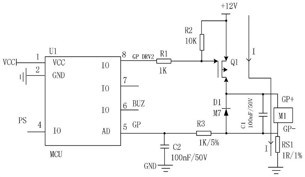
[0025] A net discharge pump detection circuit, the circuit schematic diagram is as follows figure 1 As shown, among them, U1 is the MCU; M1 is the net discharge pump, the 8th pin on U1 corresponds to the first level output pin, and the 5th pin corresponds to the voltage detection pin; R1, R2, R3, C1, C2, RS1, Q1 and D1 respectively correspond to the first resistor, the second resistor, the third resistor, the first capacitor, the second capacitor, the sampling resistor, the MOS tube and the first diode.

[0026] The working principle of the net discharge pump detecti


PUM


Abstract

The invention discloses a discharge pump detection circuit and a control method, and the discharge pump detection circuit comprises a preset power input end, an MCU and a drive detection module. The MCU comprises a first level output pin and a voltage detection pin; and the driving detection module is an access composed of a first resistor, a second resistor, a third resistor, a first capacitor, a second capacitor, a sampling resistor, an MOS transistor and a first diode. The drainage pump control method comprises the steps that the drainage pump detection circuit serves as an execution carrier, the voltages at the two ends of a sampling resistor connected with the drainage pump are detected at a preset time interval, and a real-time voltage value is obtained; the real-time voltage value is compared with a preset first threshold value and a preset second threshold value to obtain the working state of the clean discharge pump. According to the discharge pump detection circuit and the control method provided by the invention, whether the discharge pump has empty pumping can be automatically judged, and timely control is carried out to reduce noise; and meanwhile, fault alarming is carried out in time when the drainage pump is blocked.

Description


Claims


Application Information

Patent Timeline
Owner VATTI CORP LTD
Why Eureka
Try Eureka