Electric multifunctional catering vending vehicle

A multi-functional, vending vehicle technology, applied in motor vehicles, vehicles used for freight, vehicle parts, etc., can solve the problem of inconvenient opening and closing of the vending window, and achieve the effect of optimizing the structure of the carriage, highlighting the promotion prospects, and improving the stability.

Pending Publication Date: 2021-05-07
淄博齐丰餐饮设备有限公司
View PDF0 Cites 0 Cited by
  • Summary
  • Abstract
  • Description
  • Claims
  • Application Information

AI Technical Summary

Benefits of technology

This patented design allows for multiple functions such as serving food with oxygen from outside air into inside space while also allowing exhaust gases to escape through ventilation holes located near the bottom part of the cabins' interior walls. It achieves this by lifting up one side of each chamber when needed without having doors openings. Additionally, it includes features like stabilizing windows during operation, making them easier to clean afterwards if necessary. Overall, these improvements improve the functionality and usages of electrically driven multi-functioned vehicles (MFVs).

Problems solved by technology

Technological Problem: Current designs require an entire space inside the dating cart's body when it opens up during sale due to the lack of sufficient structural strength needed for safe operation. Additionally, there may exist issues such as poor visibility caused by too much light at night time (the sun) which makes it difficult to see what happens behind them while they work on their way outdoors).

Method used


Image

  • Electric multifunctional catering vending vehicle
  • Electric multifunctional catering vending vehicle
  • Electric multifunctional catering vending vehicle

Examples


Embodiment 1

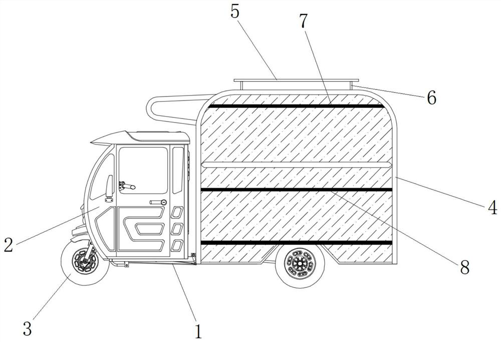
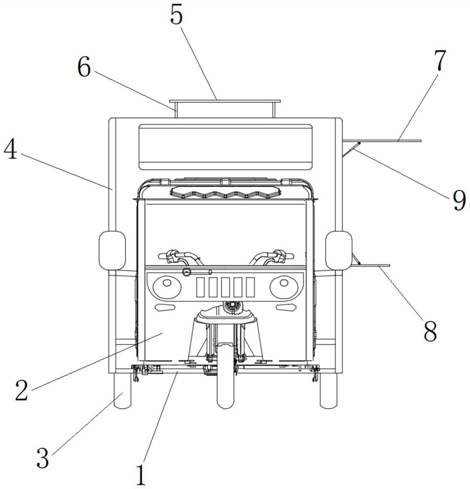
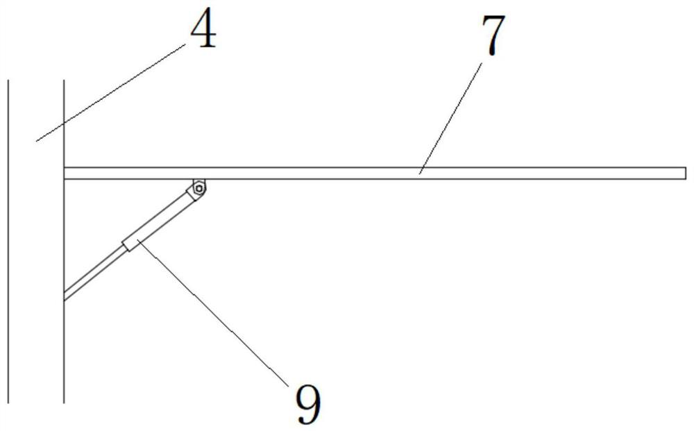
[0026] A kind of electric multifunctional food and beverage vending car, such as Figure 1~5 As shown, it includes a car body 1, a car 2, wheels 3, a car body 4, a movable roof 5, a DC electric push rod 6, an upper reversing door 7, a lower reversing door 8, and a hydraulic rod 9, wherein, in front of the car body 1 The car body 1 has a car 2 at the bottom, a wheel 3 is arranged at the lower end of the car body 1, and a compartment 4 is arranged at the rear of the car body 1. The top surface of the compartment 4 has an opening, and the movable top plate 5 is located at the opening. A DC electric push rod 6 is connected between the compartments 4, and there is a window at the side end of the compartment 4, an upper flip door 7 is hinged on the upper edge of the window, and a lower flip door 8 is hinged on the lower edge of the window. Hydraulic rods 9 are respectively connected between the upper reversing door 7 and the compartment 4 and between the lower reversing door 8 and the

Embodiment 2

[0029] A kind of electric multifunctional food and beverage vending car, such as Figure 1~5 As shown, it includes a car body 1, a car 2, wheels 3, a car body 4, a movable roof 5, a DC electric push rod 6, an upper reversing door 7, a lower reversing door 8, and a hydraulic rod 9, wherein, at the front of the car body 1 The car body 1 has a car 2 at the bottom, a wheel 3 is arranged at the lower end of the car body 1, and a compartment 4 is arranged at the rear of the car body 1. The top surface of the compartment 4 has an opening, and the movable top plate 5 is located at the opening. A DC electric push rod 6 is connected between the compartments 4, a window is provided at the side end of the compartment 4, an upper flip door 7 is hinged on the upper edge of the window, and a lower flip door 8 is hinged on the lower edge of the window. Hydraulic rods 9 are respectively connected between the upper reversing door 7 and the compartment 4 and between the lower reversing door 8 and t


PUM


Abstract

The invention provides an electric multifunctional catering vending vehicle. According to the technical scheme, the compartment structure of the catering vending truck is improved in a centralized mode. Specifically, an opening is formed in the top end of the compartment, and the movable top plate located at the opening can be driven by the direct-current electric push rod to do lifting motion, so that opening or closing of the top end of the compartment is controlled, an ascending channel can be provided for emission of smoke in the compartment, and smoke overflowing is accelerated. Besides, a clamping type door plate fixing mode is abandoned, the turnover door is hinged to the window, and a hydraulic rod is used for supporting, so that opening and closing of the window are more convenient, and better stability is achieved after the window is opened or closed. The compartment structure is fully optimized, the using effect is improved to a certain degree, and the compartment structure has outstanding popularization prospects.

Description


Claims


Application Information

Patent Timeline
Owner 淄博齐丰餐饮设备有限公司
Why Eureka
Try Eureka