Cooling device

A cooling device, cooling circuit technology, applied in cooling/ventilation/heating retrofit, battery/fuel cell control device, transportation and packaging, etc. Large and other problems, to achieve the effect of improving the effective utilization rate and reducing the overall size

Pending Publication Date: 2021-07-16
HUNAN LIANCHENG TRACK EQUIP CO LTD
View PDF0 Cites 1 Cited by
  • Summary
  • Abstract
  • Description
  • Claims
  • Application Information

AI Technical Summary

Benefits of technology

This new design allows multiple parts (converts) or devices like power generators to be cooled more effectively with less space than previous designs that only had one channel at once.

Problems solved by technology

This patented technical problem addressed in this patents relates to improving the thermal management system used on train vehicles during their run time without causing damage or noise that could harm other parts within the engine compartment.

Method used


Image

  • Cooling device
  • Cooling device
  • Cooling device

Examples


Embodiment Construction

[0039] The present invention will be further described below in conjunction with accompanying drawing.

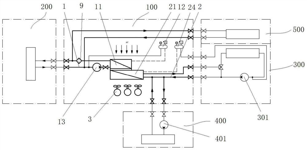
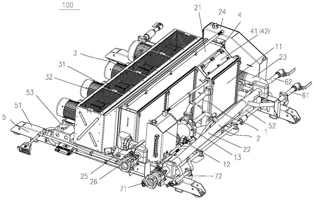
[0040] figure 1 A system schematic diagram of a cooling device 100 according to the invention is shown. like figure 1 As shown, the cooling device 100 includes two cooling circuits and an air cooling assembly 3 . One of the two cooling circuits is the converter cooling circuit 1, in which a coolant (such as water, which will be described below using water as an example, but the coolant is not limited to water) circulates therein and can be used for the converter 200. Heat dissipation and cooling. A converter radiator 11 is arranged on the converter cooling circuit 1 . The other is the fuel cell cooling circuit 2 for cooling the fuel cell 300 , in which a coolant (such as water will be used as an example to describe later, but the coolant is not limited to water). Furthermore, a fuel cell radiator 21 is provided on the fuel cell cooling circuit. The air cooling assembly 3


PUM


Abstract

The invention provides a cooling device, which comprises: a converter cooling loop, wherein a converter radiator is arranged on the converter cooling loop; a fuel cell cooling loop, wherein a fuel cell radiator is arranged on the fuel cell cooling loop; and an air cooling assembly, wherein the air cooling assembly can perform heat dissipation and cooling on the converter radiator and the fuel cell radiator, the converter cooling loop can perform heat dissipation on a converter, and the fuel cell cooling loop can perform heat dissipation on a fuel cell. The cooling device has the advantages of high heat exchange efficiency, light weight, low noise and capability of accurately controlling energy consumption.

Description


Claims


Application Information

Patent Timeline
Owner HUNAN LIANCHENG TRACK EQUIP CO LTD
Why Eureka
Try Eureka