Bar feeding device for cutting machine

A supply device and cutting machine technology, applied in metal processing equipment, welding equipment, manufacturing tools, etc., can solve the problems of increasing labor intensity and low safety of workers

Active Publication Date: 2021-08-13
上海长特锻造有限公司
View PDF12 Cites 4 Cited by
  • Summary
  • Abstract
  • Description
  • Claims
  • Application Information

AI Technical Summary

Problems solved by technology

[0004] In view of the above-mentioned related technologies, the inventor believes that feeding mater

Method used


Image

  • Bar feeding device for cutting machine
  • Bar feeding device for cutting machine
  • Bar feeding device for cutting machine

Examples


Embodiment Construction

[0039] Attached to the following Figure 1-7 This application will be described in further detail.

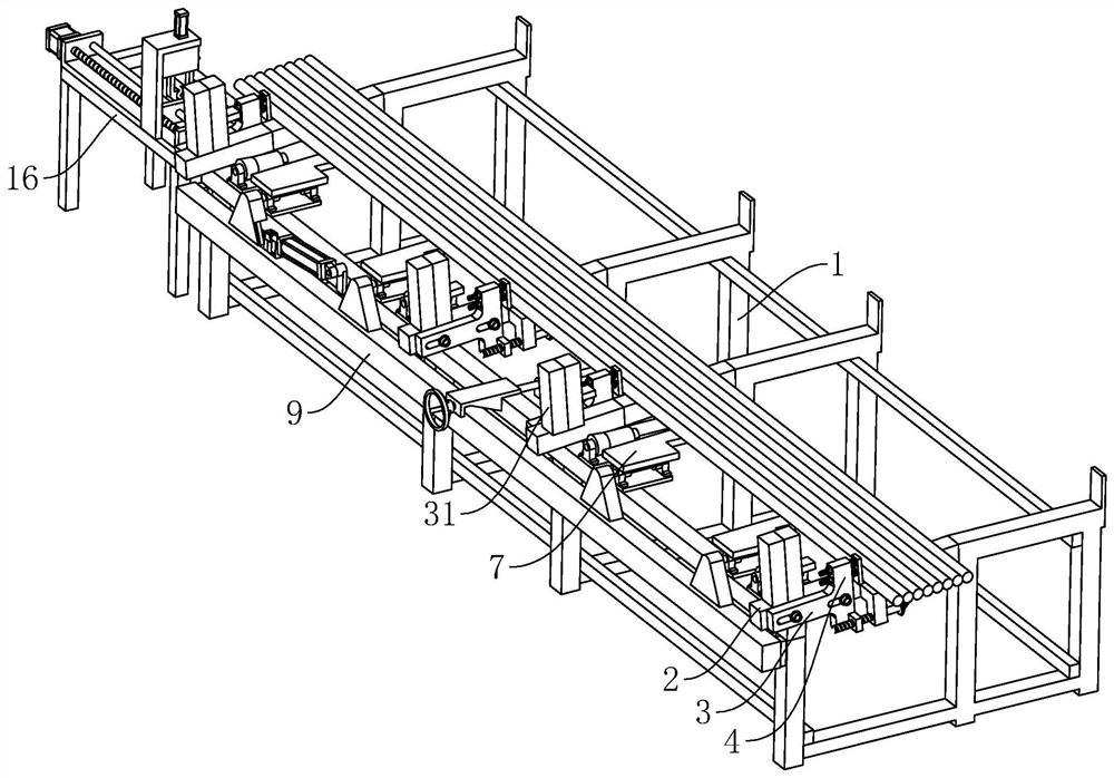
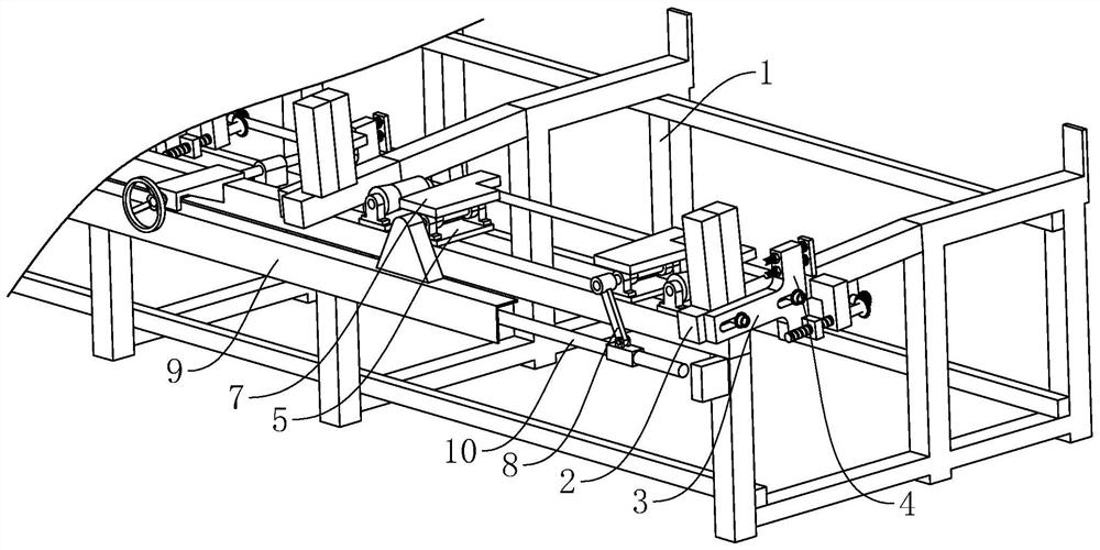
[0040] The embodiment of the present application discloses a bar supply device for a cutting machine. refer to figure 1 , The bar feeding device for cutting machine includes a frame 1, a discharging frame 2 and a feeding mechanism. The outline of the frame 1 is rectangular, the top of the frame 1 is inclined, and the height of the top of the frame 1 is along the width of the frame 1. The direction is gradually lowered, and both the feeding rack 2 and the feeding mechanism are installed on the top of the rack 1 at a lower height.

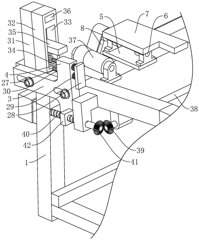
[0041] refer to figure 1 and figure 2 , there are several feeding racks 2 arranged along the length direction of the rack 1, and an adjusting plate 3 is installed vertically on one side of the discharging rack 2, and the top of the adjusting plate 3 is close to the top of the rack 1 The higher position is integrally connected with the first positio


PUM


Abstract

The invention relates to a bar feeding device for a cutting machine, and relates to the field of feeding devices for cutting machines. The bar feeding device comprises a rack, several discharging frames arranged on the rack and a feeding mechanism arranged on the rack, the top of the rack is obliquely arranged, the feeding mechanism comprises an overturning assembly arranged on the rack and a pushing assembly arranged on the rack and located on one side of the overturning assembly, the discharging frame, the feeding mechanism and the overturning assembly are all located at the lower position of the top of the rack, the discharging frame is located on one side of the overturning assembly, the discharging frame is provided with a first positioning plate used for positioning bars on the rack, the overturning assembly is used for overturning the bars on the rack to the discharging frame, and the pushing assembly is used for pushing the bars on the discharging frame. According to the bar feeding device, the bars can be automatically fed, and the bars can be conveniently cut by the cutting machine.

Description


Claims


Application Information

Patent Timeline
Owner 上海长特锻造有限公司
Why Eureka
Try Eureka