Novel swing welding track planning method for welding robot

A welding robot and trajectory planning technology, applied in welding equipment, auxiliary welding equipment, welding/cutting auxiliary equipment, etc., can solve the problems of welding quality influence, speed and acceleration step, etc., and achieve improved weld quality, continuous acceleration, The effect of continuous angular acceleration

Pending Publication Date: 2021-08-27
WUXI XINJIE ELECTRICAL
View PDF0 Cites 0 Cited by
  • Summary
  • Abstract
  • Description
  • Claims
  • Application Information

AI Technical Summary

Benefits of technology

The swash-path programming system described by this inventor allows for precise control on how well different materials are joined together without causing any issues or defects that could affect their performance. It also includes an algorithm called Cyclotronics (C), which helps create smooth curves with high accuracy when interpolated between two points within certain limits. These technical improvements make it possible to achieve better results compared to traditional methods like spiraling rods used alone.

Problems solved by technology

This patented technology solves issues related to wider seams during laser beam welded joints by providing both linear and swivel movements for the robotic arm used to move along its path. However, current methods are slow or require significant accelerations at each step due to their use of an equation called Sine - Cosine Function (SCO).

Method used


Image

  • Novel swing welding track planning method for welding robot
  • Novel swing welding track planning method for welding robot
  • Novel swing welding track planning method for welding robot

Examples


Embodiment Construction

[0090] The present invention will be described in further detail below according to the drawings and embodiments. The described embodiments are only some, not all, embodiments of the present invention. Based on the embodiments of the present invention, all other embodiments obtained by persons of ordinary skill in the art without creative efforts fall within the protection scope of the present invention.

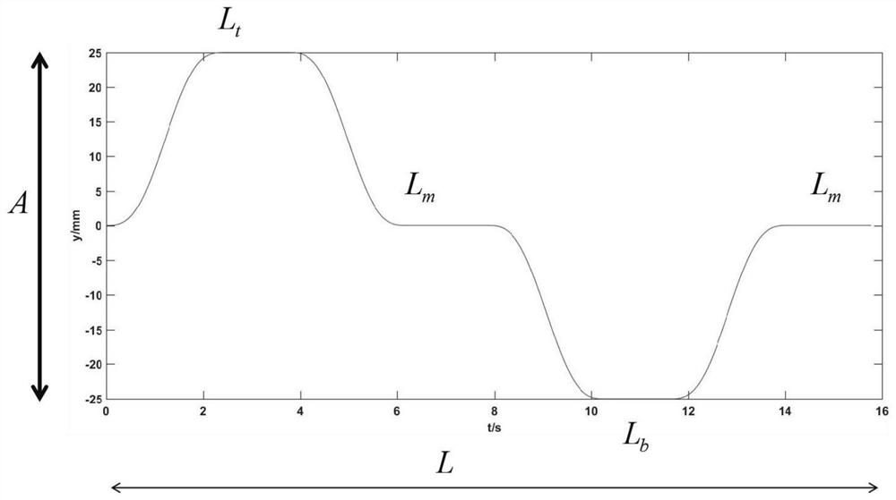
[0091] This method first needs to determine the welding parameters and obtain the teaching point parameters; then determine the swing plane, and obtain the parameters required for interpolation through the speed planning of the entire trajectory in the weld coordinate system; then according to the idea of ​​trajectory superposition , the cycloid trajectory planning method is adopted in the direction perpendicular to the weld seam, and the isochronous linear trajectory planning method is adopted along the weld seam direction. The plan is as follows:

[0092] A novel weaving we


PUM


Abstract

The invention relates to the technical field of automatic welding, in particular to a novel swing welding track planning method for a welding robot. The method comprises: firstly, determining welding parameters to obtain teaching point position parameters; then, determining a swing plane, and obtaining parameters needed by interpolation through speed planning of the whole track under a welding seam coordinate system; according to the idea of trajectory superposition, using a cycloid trajectory planning method in the direction perpendicular to the weld joint, and using an equal-time linear trajectory planning method in the direction of the weld joint. The method can ensure that the angular velocity and the angular acceleration of each joint are continuous in the welding process of the robot, and can effectively improve the welding seam quality. A cycloid displacement piecewise function is used in a direction perpendicular to the welding main track, and it can be guaranteed that the speed and the acceleration are continuous in the whole swing welding process.

Description


Claims


Application Information

Patent Timeline
Owner WUXI XINJIE ELECTRICAL
Why Eureka
Try Eureka