Liquid chromatographic column pipe body grinding device
A liquid chromatography column and tube body technology, applied in the field of liquid chromatography column tube body grinding device, can solve problems such as low efficiency, troublesome left and right dumping, troublesome operation, etc.
- Summary
- Abstract
- Description
- Claims
- Application Information
AI Technical Summary
Benefits of technology
Problems solved by technology
Method used
Image

Examples
Embodiment 1
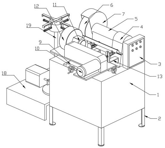
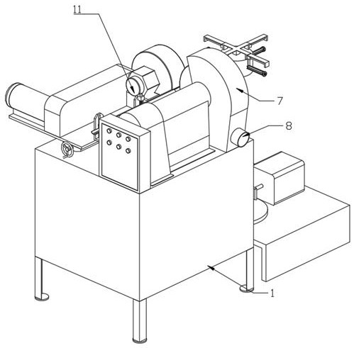
[0029] Such as Figure 1-7 As shown, a liquid chromatography column tube body grinding device provided by the present invention includes a body 1 and a support bracket 18, supporting legs 2 are respectively provided on the walls around the bottom of the body 1, and the front end wall body on one side of the top of the body 1 An electric control box 3 is arranged on the top of the body 1. A chassis 4 is arranged on the wall behind the electric control box 3 on the top of the body 1. A transmission box 5 is arranged on the rear end wall of the chassis 4 on the top of the body 1. The rear end shaft of the transmission box 5 is Grinding wheel 6 is arranged on it, and protective cover 7 is also provided on the rear end wall of transmission box 5, and waste residue pipe 8 is provided in the back wall of protective cover 7, and slide table 9 is provided on the other side wall of body 1 top, A first motor 10 is provided on the front end wall of the top of the slide table 9, a speed reduc
Embodiment 2
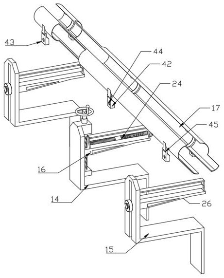
[0031] On the basis of Example 1, as image 3 , Figure 4 and Figure 5In the shown placement mechanism of a liquid chromatography column tube body grinding device, the bottom wall of the first fixing frame 14 is fixedly installed on the wall of the top of the body 1 close to the side of the transmission box 5 by welding. The frame 14 side wall body is also provided with a first fixed block 28, the first fixed block 28 side wall body is fixedly installed on the first fixed frame 14 side wall body by welding, the first fixed frame 14 side A second fixed block 29 is also arranged on the wall above the first fixed block 28, and the second fixed block 29 is fixedly installed on the side wall of the first fixed frame 14 by welding, and the top of the first support beam 16 The wall body is also provided with a third fixed mount 25, and the second fixed block 29 is also provided with a second adjustment shaft 31 in the wall body. The outer wall below the second adjustment shaft 31 is
Embodiment 3
[0033] On the basis of Example 2, such as image 3 , Figure 4 and Figure 5 As shown, the side walls at the bottom of the third fixing frame 25 are fixedly installed on the side walls at the top of the first supporting beam 16 by welding respectively, and a turning groove 38 is also opened in the side walls of the third fixing frame 25 , the first adjusting shaft 24 is installed in the rotating groove 38 through the rotating block on one side of the outer wall, and the other side wall of the first adjusting shaft 24 is installed in the groove on the inner wall of the third fixed frame 25 side, the second The outer walls on both sides of the first adjustment shaft 24 are respectively provided with second threads 39, and the side wall body of the first adjustment shaft 24 is also provided with a knob block 40, and the knob block 40 is fixedly installed on the first adjustment shaft 24 by welding. On the side wall body, the bottom side walls of the fourth fixing frame 27 are resp
PUM
 Abstract
Description
Claims
Application Information
 - R&D Engineer
- R&D Manager
- IP Professional
- Industry Leading Data Capabilities
- Powerful AI technology
- Patent DNA Extraction
Browse by: Latest US Patents, China's latest patents, Technical Efficacy Thesaurus, Application Domain, Technology Topic.
© 2024 PatSnap. All rights reserved.Legal|Privacy policy|Modern Slavery Act Transparency Statement|Sitemap