Electrostatic spinning nozzle structure based on capillary principle and application method thereof

An electrospinning and capillary technology, applied in fiber processing, textiles and papermaking, filament/thread forming, etc., can solve the problems of increasing the diffusion surface of spinning solution, achieve novel structure, improve yield and quality, increase The effect of a large diffusion surface

Active Publication Date: 2021-11-30
鑫合德(清远)智能科技发展有限公司
View PDF5 Cites 0 Cited by
  • Summary
  • Abstract
  • Description
  • Claims
  • Application Information

AI Technical Summary

Benefits of technology

The technical effect of this patented technology relating to an improved apparatus for producing fibers by applying electricity onto threads made out of polymers or other materials has been developed over time due to its ability to efficiently remove unwanted substances such as solvents (volatile organic compounds) released during production processes without damaging sensitive components inside these devices. This results in higher yields and purities of produced fibers compared to traditional methods like dry cleaning techniques which require frequent maintenance.

Problems solved by technology

Technological Problem addressed in this patents relates to improving the performance or productivity of elecro spun fiber generators (ESFs) without sacrificing their ability to produce small amounts of material at very fast speeds. Current methods involve either needling or needled nozzels that limit throughput compared to other techniques like rotating disk elecymetry. Highly efficient elec trospray devices would help achieve these goals while maintaining good quality materials produced from ESFs.

Method used


Image

  • Electrostatic spinning nozzle structure based on capillary principle and application method thereof
  • Electrostatic spinning nozzle structure based on capillary principle and application method thereof
  • Electrostatic spinning nozzle structure based on capillary principle and application method thereof

Examples


Embodiment Construction

[0026] The technical solutions of the present invention will be further described below in conjunction with the accompanying drawings and through specific implementation methods.

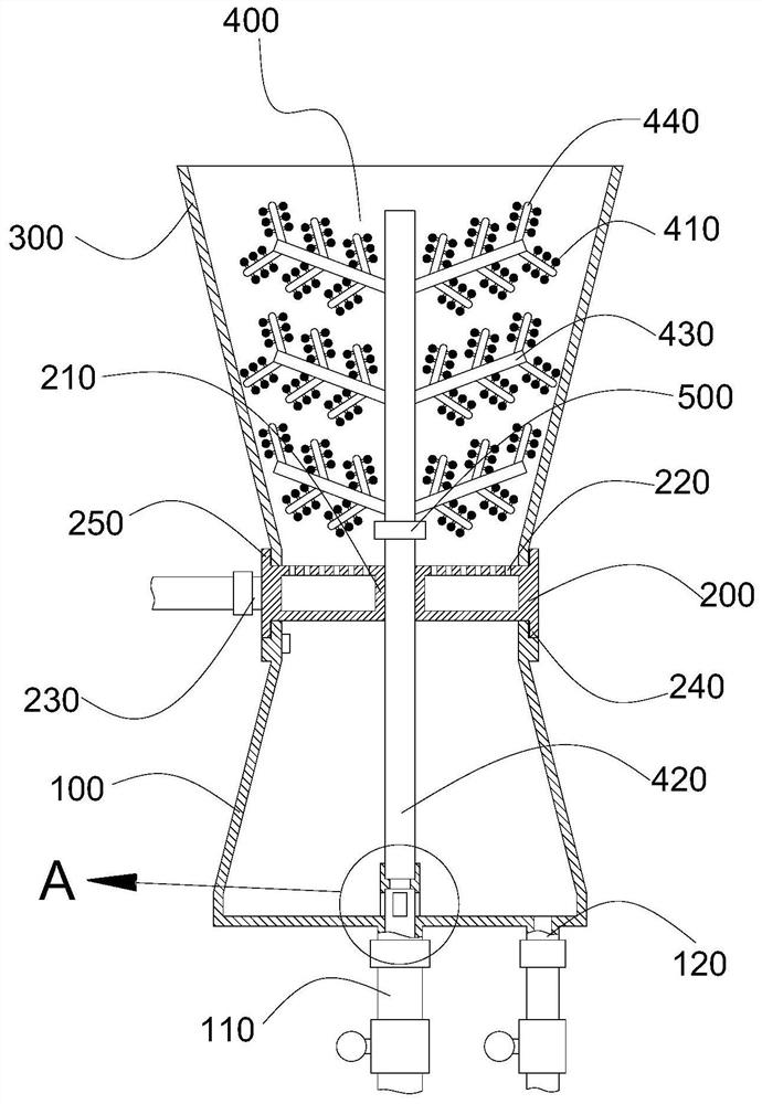
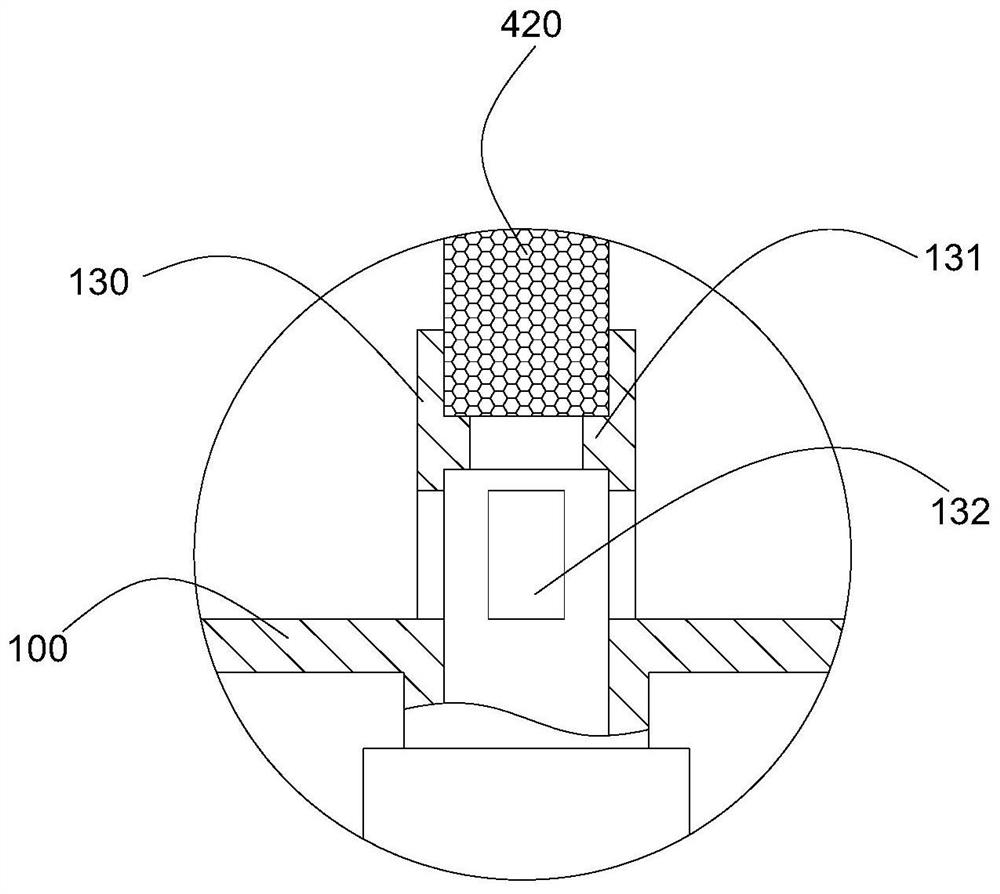
[0027] Such as Figure 1 to Figure 4 As shown, a specific embodiment of the present invention discloses an electrospinning nozzle structure based on the capillary principle, including a liquid storage tank 100, a splitter box 200 installed on the top of the liquid storage tank 100, and a guide tube installed on the top of the splitter box 200. The flow tube 300 adopts a detachable structure, which is convenient for production, processing and assembly; the middle part of the flow box 200 is provided with a socket 210 that runs through the upper and lower walls, and the top surface of the flow box 200 is provided with a plurality of air outlets 220, and the air outlets 220 and The distribution box 200 is internally connected, and the side wall of the distribution box 200 is connected with a gas supply pi


PUM


Abstract

The invention provides an electrostatic spinning nozzle structure based on the the capillary principle and an application method thereof. The electrostatic spinning nozzle structure comprises a liquid storage barrel and a flow dividing box installed at the top of the liquid storage barrel, wherein a flow guide cylinder is installed at the top of the flow dividing box; an inserting cylinder penetrating through the upper wall surface and the lower wall surface is arranged in the middle of the flow dividing box; a plurality of air outlet holes are formed in the top surface of the flow dividing box and communicate with the interior of the flow dividing box; an air supply pipe communicates with the side wall of the flow dividing box and is used for communicating with external high-pressure air supply equipment; the bottom of the liquid storage barrel communicates with a liquid supply pipe and a liquid discharge pipe; the pipe diameter of the liquid supply pipe is larger than the pipe diameter of the liquid discharge pipe; a volatilization structure is arranged in the flow guide cylinder; the bottom of the volatilization structure penetrates through the inserting cylinder and extends into the liquid storage barrel; the upper part of the volatilization structure is of a tree-shaped structure; and a plurality of sea urchin-shaped spray heads are installed on branches of the volatilization structure. The structure is novel, a needle-free structure is adopted, the application method is simple, the problem of spray head blockage can be prevented, the diffusion surface of a spinning solution can be effectively increased, and the yield and the quality of spinning fibers are improved.

Description


Claims


Application Information

Patent Timeline
Owner 鑫合德(清远)智能科技发展有限公司
Why Eureka
Try Eureka