LPG (Liquefied Petroleum Gas) fuel pipeline control method

A technology of fuel pipeline and control method, which is applied in charging system, combustion engine, internal combustion piston engine, etc., can solve the problem of inability to meet the use of LPG fuel, and achieve the effect of reducing cost and having broad application prospects.

Active Publication Date: 2022-03-01
CHINA MERCHANTS HEAVY IND SHENZHEN
View PDF14 Cites 4 Cited by
  • Summary
  • Abstract
  • Description
  • Claims
  • Application Information

AI Technical Summary

Problems solved by technology

[0003] LPG needs a high pressure of 50bar±2 and a temperature of 35℃±8 to enter the host. LPG is stored in the fuel tank at a low temperature of -45℃, and the storage pressure is lower than 5bar, so LPG needs to be pressuri

Method used


Image

  • LPG (Liquefied Petroleum Gas) fuel pipeline control method
  • LPG (Liquefied Petroleum Gas) fuel pipeline control method

Examples


Embodiment Construction

[0030] The following will clearly and completely describe the technical solutions in the embodiments of the present invention with reference to the accompanying drawings in the embodiments of the present invention. Obviously, the described embodiments are only some, not all, embodiments of the present invention. Based on the embodiments of the present invention, all other embodiments obtained by persons of ordinary skill in the art without making creative efforts belong to the protection scope of the present invention.

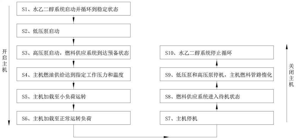
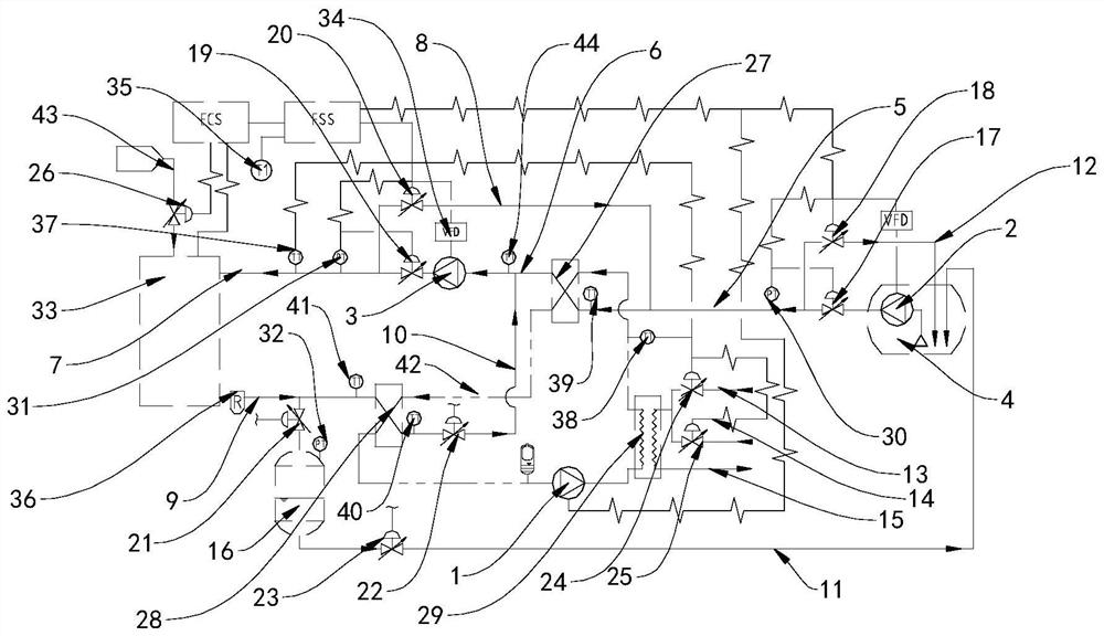
[0031] see Figure 1-2 , the invention discloses a method for controlling an LPG fuel pipeline, comprising the following steps:

[0032] S1, the water glycol system is started and circulated to a steady state, when the water glycol system is started and circulated to a stable state, the water glycol pipe 42 is filled with water glycol liquid, and the water glycol pump 1 is started to allow The liquid circulates in the water glycol pipe 42 in a closed loop, open


PUM


Abstract

The invention discloses an LPG fuel pipeline control method, and relates to the technical field of LNG power ship pipeline control. Comprising the steps that a water glycol system is started and circulated to a stable state, a low-pressure pump is started, a high-pressure pump is started, a fuel supply system reaches a preparation state, fuel supply of a main engine reaches specified working pressure and temperature, the main engine is loaded to small-load operation, the main engine is loaded to normal operation load, and the main engine is stopped. The engine in the marine main engine can use LPG as fuel, the cost is reduced, meanwhile, the fuel can be automatically heated, pressurized, cooled, decompressed, inerted and subjected to gas-liquid separation operation, surplus overpressure fuel can be refluxed and utilized, through a water glycol system, the LPG fuel can be heated and cooled, and the fuel can be recycled. The temperature of the device can be adjusted by other heat sources and cold sources, the device is automatically controlled to operate through a fuel supply system, the device is matched with a host control system to start and stop, automatic operation is achieved, economic benefits are met, and the application prospect is wide.

Description


Claims


Application Information

Patent Timeline
Owner CHINA MERCHANTS HEAVY IND SHENZHEN
Why Eureka
Try Eureka