Vaporization system and semiconductor process equipment

A process equipment, semiconductor technology, applied in semiconductor/solid-state device manufacturing, sustainable manufacturing/processing, climate sustainability, etc., can solve the problem of difficulty in controlling flow rate and affecting the uniformity of a single wafer of boron diffusion reaction. Multiple wafers Uniformity, reducing the uniformity of the oxidation treatment process, etc., to achieve the effect of improving efficiency and uniformity

Pending Publication Date: 2022-07-12
BEIJING NAURA MICROELECTRONICS EQUIP CO LTD
View PDF0 Cites 0 Cited by
  • Summary
  • Abstract
  • Description
  • Claims
  • Application Information

AI Technical Summary

Benefits of technology

This patented technology provides a way to efficiently evacuate gases during chemical processes used in manufacturing electronic devices such as integrated circuits (IC). By combining two different liquids together at once through various techniques like spray blending, it allows for complete gasification without leaving behind residue on surfaces being processed next time. Additionally, this method helps control how much material enters each processing chamber based upon their contents. Overall, these technical improvements improve productivity while minimizing environmental impact.

Problems solved by technology

This patented technical problem addressed in this patents relates to improving the quality of chemical reactions during manufacturing of semiconductors such as solar cells due to improved uniformity when controllably delivering precise amounts of reactants onto specific areas within these devices.

Method used


Image

  • Vaporization system and semiconductor process equipment
  • Vaporization system and semiconductor process equipment

Examples


Embodiment Construction

[0034] In order for those skilled in the art to better understand the technical solutions of the present invention, the vaporization system and semiconductor process equipment provided by the present invention will be described in detail below with reference to the accompanying drawings.

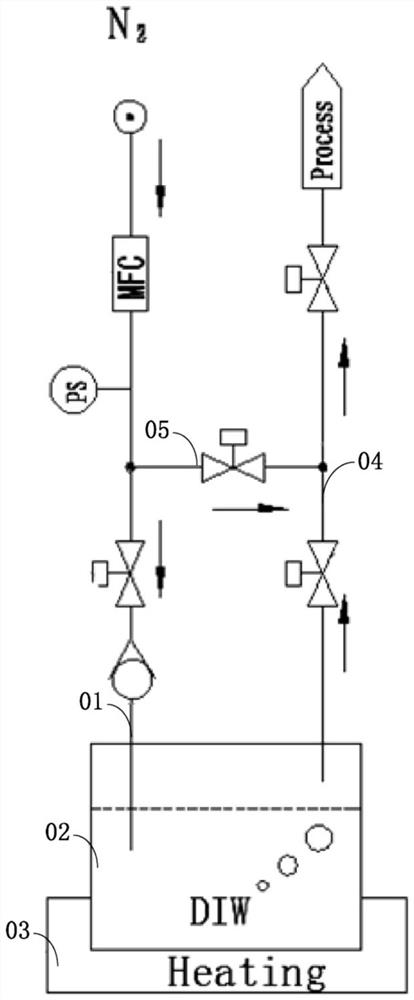
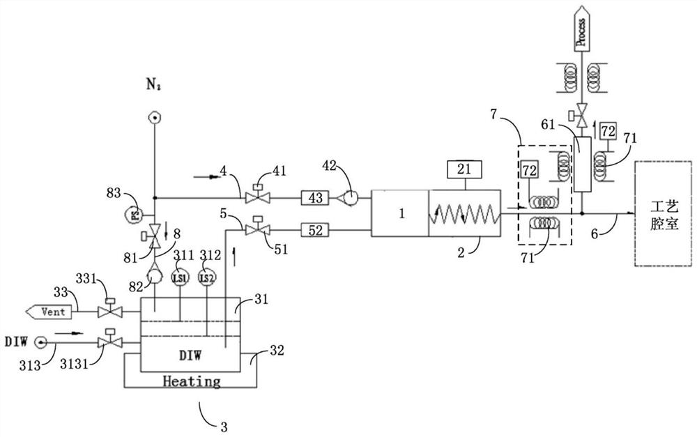
[0035] The present embodiment provides a vaporization system for delivering vapor to a process chamber of a semiconductor process equipment. Please refer to figure 2 , the vaporization system includes: jet mixer 1, mixing heater 2, process liquid source 3 and multiple pipelines. The process liquid source 3 is used for storing and outputting process liquid, and specifically, the process liquid includes deionized water.

[0036] The above-mentioned pipelines include an air inlet pipeline 4 , a liquid inlet pipeline 5 and an air outlet pipeline 6 . The first inlet of the jet mixer 1 is communicated with an external gas source through the air inlet pipeline 4, and the external gas source is used


PUM


Abstract

The invention provides a vaporization system and semiconductor process equipment. The vaporization system comprises a jet mixer, a mixing heater, a process liquid source and a plurality of pipelines, wherein the process liquid source is used for storing and outputting process liquid; two inlets of the jet mixer are respectively communicated with an external gas source and a process liquid source; a first inlet of the jet mixer is communicated with a gas source through a gas inlet pipeline, a second inlet of the jet mixer is communicated with a process liquid source through a liquid inlet pipeline, and the jet mixer is used for mixing carrier gas input by the gas source and process liquid input by the process liquid source to form a mist mixture; an inlet of the mixing heater is communicated with an outlet of the jet mixer, the mixing heater is used for heating the fog-state mixture so that the fog-state mixture can be gasified into steam, and an outlet of the mixing heater is communicated with the process chamber through a gas outlet pipeline. The vaporization system provided by the invention can effectively ensure that the process liquid is fully gasified, and can effectively control the flow of the formed steam.

Description


Claims


Application Information

Patent Timeline
Owner BEIJING NAURA MICROELECTRONICS EQUIP CO LTD
Why Eureka
Try Eureka