Bar clamping guide wheel mechanism for refiner

A technology of guide wheel mechanism and fine grinding machine, which is applied in the direction of grinding machine tool parts, grinding drive device, grinding workpiece support, etc., and can solve the problem of inability to meet the requirements of high-precision micro-drilling and the concentricity of bar and drill pin Low-level problems, to ensure stability, meet processing needs, and improve concentricity

Pending Publication Date: 2022-08-05
深圳市友创智能设备有限公司
View PDF0 Cites 0 Cited by
  • Summary
  • Abstract
  • Description
  • Claims
  • Application Information

AI Technical Summary

Problems solved by technology

At present, the clamping mechanism that can realize rotation clamps the workpiece through the jaws, and then drives the jaws to rotate, thereby driving the workpiece to rotate; during the processing of this kind of clamping mech

Method used


Image

  • Bar clamping guide wheel mechanism for refiner
  • Bar clamping guide wheel mechanism for refiner
  • Bar clamping guide wheel mechanism for refiner

Examples


Embodiment Construction

[0022] Unless otherwise defined, all technical and scientific terms used herein have the same meaning as commonly understood by one of ordinary skill in the art of this application; terms used herein in the specification of the application are for the purpose of describing particular embodiments only , is not intended to limit the application; the terms "comprising" and "having" and any variations thereof in the description and claims of this application and the above description of the drawings are intended to cover non-exclusive inclusion. The terms "first", "second" and the like in the description and claims of the present application or the above drawings are used to distinguish different objects, rather than to describe a specific order.

[0023] Reference herein to an "embodiment" means that a particular feature, structure, or characteristic described in connection with the embodiment can be included in at least one embodiment of the present application. The appearances of


PUM


Abstract

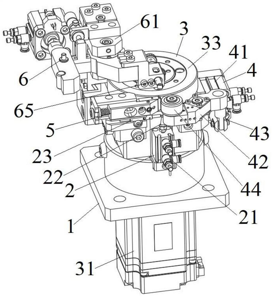
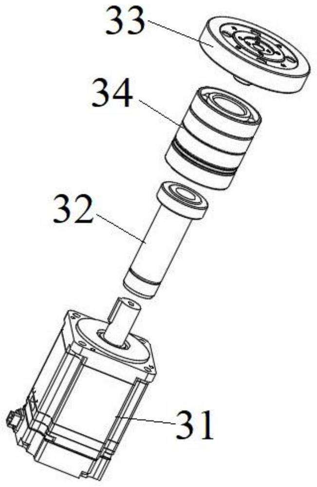
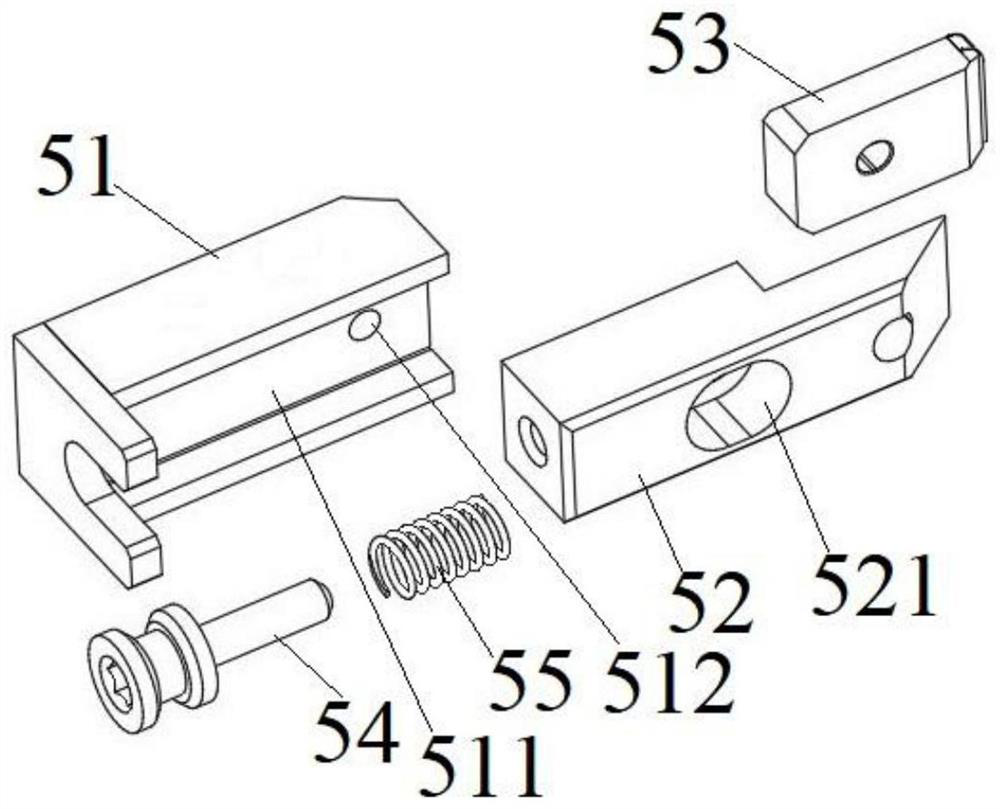
The bar clamping guide wheel mechanism for the refiner comprises a fixing base, a bar placing mechanism, a guide wheel mechanism and a pressing wheel limiting mechanism are arranged on the fixing base, the bar placing mechanism is used for placing a to-be-machined bar, the guide wheel mechanism is used for driving the to-be-machined bar to rotate, and the pressing wheel limiting mechanism is used for limiting the to-be-machined bar to rotate. The pressing wheel limiting mechanism is used for limiting a bar to be machined on the bar placement mechanism; the guide wheel mechanism comprises a rotary driving mechanism and a guide wheel, the rotary driving mechanism is connected with the fixed seat, the output end of the rotary driving mechanism is connected with the guide wheel, and the rotary driving mechanism is used for driving the guide wheel to rotate. The guide wheel is driven by the rotary driving mechanism to rotate, and the guide wheel drives the bar to synchronously rotate on the bar placement mechanism, so that the accurate grinding machine can uniformly grind the outer circumferential surface of the drill point, the concentricity of the bar and the drill point is improved, and the machining requirement of a high-precision micro drill is met.

Description


Claims


Application Information

Patent Timeline
Owner 深圳市友创智能设备有限公司
Why Eureka
Try Eureka