Cleaning device for outer side of curtain wall

A technology for cleaning devices and curtain walls, which can be used in carpet cleaning, equipment cleaning, floor cleaning, etc. It can solve problems such as hidden safety hazards in the cleaning of outer curtain walls, and achieve the effect of reducing the possibility of falling.

Pending Publication Date: 2022-08-09
查鹏
View PDF7 Cites 0 Cited by
  • Summary
  • Abstract
  • Description
  • Claims
  • Application Information

AI Technical Summary

Benefits of technology

This patented technology allows for easy installation onto external surfaces such as inside walls without having workers constantly manually scour them over multiple times. By driving fans at different speeds, dust particles are removed along with water droplets, resulting in improved efficiency compared to traditional methods like manual scrubbing. Additionally, there may exist devices attached to the exterior of these structures to help remove debris more efficiently. Overall, this technical solution provides better results than previous solutions.

Problems solved by technology

This patented describes an apparatus used by workers on high-rise buildings during maintenance work or other activities that require elevated access inside walls such as window blinds. These devices have long lifespan components like cords attached at their ends with hooks called tethers. However, these tools may be dangerous because they could accidentally drop them if there were no way to stop falling down safely without being taken out of position.

Method used


Image

  • Cleaning device for outer side of curtain wall
  • Cleaning device for outer side of curtain wall
  • Cleaning device for outer side of curtain wall

Examples


Embodiment 1

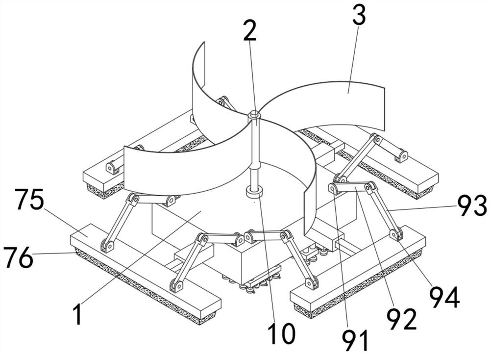
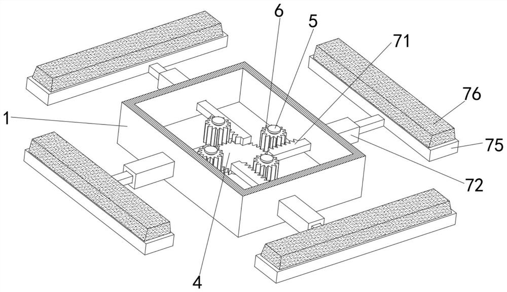
[0033] see figure 1 , 2Shown in -6: a cleaning device for the outside of the curtain wall, including a box 1, a first-level rotating mechanism is installed at the center of the box 1, and the first-level rotating mechanism is connected with four second-level rotating mechanisms, each of which is a second-level rotating mechanism. A cleaning mechanism is connected; the first-level rotating mechanism includes a rotating rod 2, a fan blade 3 and a rotating disk 4. The outer surface of the rotating disk 4 is fixed with four groups of first teeth in the form of an annular array, and the center of the side wall of the rotating disk 4 is fixed. It is fixed with one end of the rotating rod 2, and the other end of the rotating rod 2 passes through the center of the inner wall of the box body 1 and is fixed with a plurality of fan blades 3; It is rotatably installed inside the rotating sleeve 10; each secondary rotating mechanism includes a rotating shaft 5 and a gear 6, the gear 6 is rot

Embodiment 2

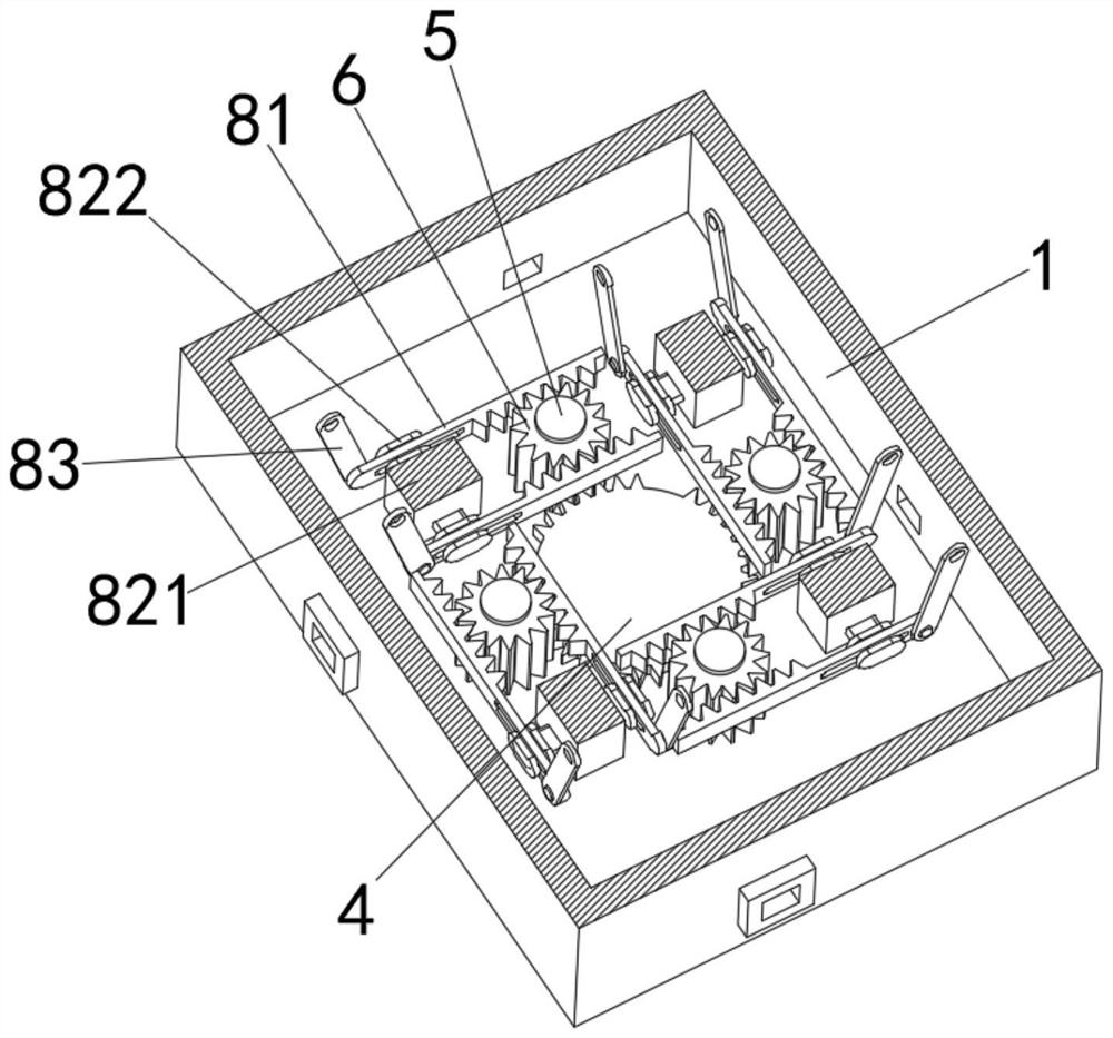
[0036] see image 3 , 5 Shown in -7: a cleaning device for the outer side of the curtain wall, including a box body 1, a first-level rotating mechanism is installed at the center of the box body 1, and the first-level rotating mechanism is connected with four second-level rotating mechanisms, each of which is a second-level rotating mechanism. Two moving mechanisms are connected; the first-level rotating mechanism includes a rotating rod 2, a fan blade 3 and a rotating disk 4, and the outer surface of the rotating disk 4 is fixed with four groups of first teeth in the form of an annular array, and the side wall of the rotating disk 4 is The center is fixed with one end of the rotating rod 2, and the other end of the rotating rod 2 passes through the center of the inner wall of the box body 1 and is fixed with a plurality of fan blades 3; The rod 2 is rotatably installed inside the rotating sleeve 10; each secondary rotating mechanism includes a rotating shaft 5 and a gear 6, the


PUM


Abstract

The invention relates to the technical field of curtain wall cleaning, and discloses a cleaning device for the outer side of a curtain wall, the cleaning device comprises a box body, a first-stage rotating mechanism is mounted at the center of the box body, the first-stage rotating mechanism is connected with four second-stage rotating mechanisms, and each second-stage rotating mechanism is connected with a cleaning mechanism and two moving mechanisms; the first-stage rotating mechanism comprises a rotating rod, fan blades and a rotating disc, and four sets of first clamping teeth are fixed to the outer surface of the rotating disc in an annular array mode. In the process of cleaning the outer side of the curtain wall, the device can be installed on the outer side of the curtain wall, wind power can blow a plurality of fan blades, and the multiple fan blades can drive a rotating disc to rotate through a rotating rod in the rotating process; and the rotating disc can drive the gear to rotate through each group of first clamping teeth on the outer surface in the rotating process, so that the gear can drive the cleaning plate to move through the toothed bar in the rotating process.

Description


Claims


Application Information

Patent Timeline
Owner 查鹏
Why Eureka
Try Eureka