Picture processing apparatus and method and recording medium

A technology of image processing and equipment, applied in color signal processing circuits, image communication, picture duplicators, etc., can solve the problems of increased precision of focus correction, uneven density grating, focus cannot be corrected, etc., to reduce power consumption, high precision effect

Inactive Publication Date: 2005-01-12
SONY CORP
View PDF0 Cites 0 Cited by
  • Summary
  • Abstract
  • Description
  • Claims
  • Application Information

AI Technical Summary

Benefits of technology

The technical effect that this technology allows for smaller focal-correction circuits and deflectors while reducing their energy usage compared to traditional methods like phase locked loops (PLLs). This results in higher precision and faster convergence times when performing focus corrections on images captured by cameras or sensing devices equipped with image processing capabilities such as smartphones or tablets.

Problems solved by technology

This patented technical solution describes different ways to improve the performance of focused correction devices called CRTs. These techniques involve improving resolution and reducing size requirements while maintaining accurate alignment control over the entire picture being scanned. Additionally, these techniques include compensation functions where the correction process involves updating predetermined settings instead of just relying upon previous values. Overall, these improvements help reduce costs associated with manufacture and operation processes.

Method used


Image

  • Picture processing apparatus and method and recording medium
  • Picture processing apparatus and method and recording medium
  • Picture processing apparatus and method and recording medium

Examples


Embodiment Construction

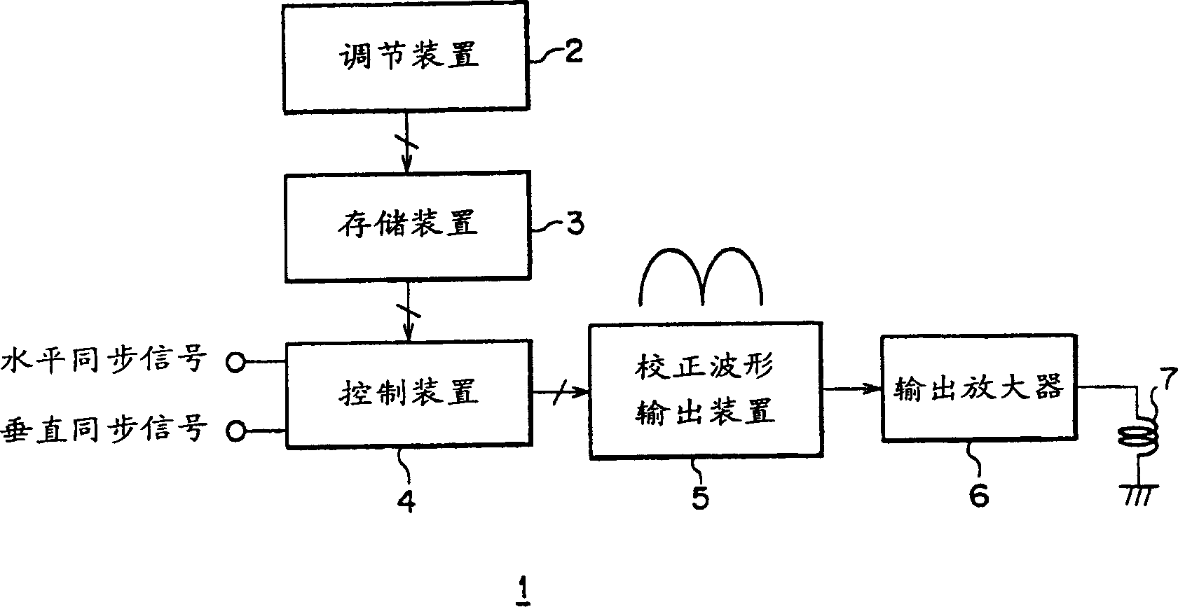
[0043] The display device applying the present invention independently adjusts the output timing of the red, green, and blue output video signals relative to the input digital video signal to individually correct the position error of the three-color video signal, and can simultaneously correct when the video signal is displayed Focus and image distortion when on a cathode ray tube.

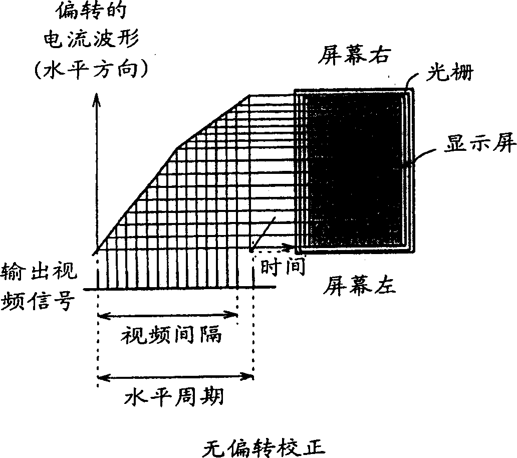
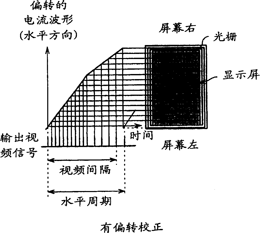
[0044] 5A and 5B show that by independently adjusting the output timing of the video signals of the red, green, and blue colors in the horizontal period, horizontal linearity correction and focus correction can also be performed. FIG. 5A shows a display screen in which such correction as described above is not performed, and FIG. 5B shows another display screen in which such correction as described above is performed. It can be seen from FIG. 5B that by independently adjusting the output timing of the red, green, and blue colors in the time base direction, horizontal linear correction and horizontal foc


PUM


Abstract

An image processing apparatus is disclosed by which correction of convergence and correction of distortion of an image can be performed with a high degree of accuracy. Correction data to be used for correction of position errors of the three colors of red, green and blue obtained by an adjustment apparatus in advance are stored in a storage section. The stored correction data are outputted to a correction waveform outputting section through a control circuit when necessary. The correction waveform outputting section produces correction waveforms based on the correction data inputted thereto and outputs the correction waveforms to a clock signal generation circuit. The clock signal generation circuit generates clocks, and the video data of red, green and blue stored in the memory are read out in response to the clock signals.

Description


Claims


Application Information

Patent Timeline
Owner SONY CORP
Why Eureka
Try Eureka