Fiber optic sight pin

Inactive Publication Date: 2005-06-30
AFSHARI ABBAS BEN
View PDF84 Cites 27 Cited by
  • Summary
  • Abstract
  • Description
  • Claims
  • Application Information

AI Technical Summary

Benefits of technology

[0011] In accordance with the present invention, a sight pin for use with a bow sight includes an elongate segment of fiber optic material used to form a sighting indicia at one of its terminal ends.

Problems solved by technology

It is also well-known in the art that despite the light-gathering capabilities of fiber optic elements which render sighting devices more useful in low-light conditions (e.g., dusk), there is a point at which the ambient light is so low that the fiber optic element is no longer capable of gathering sufficient light to provide any illumination.
While others in the art have disclosed the u

Method used


Image

  • Fiber optic sight pin
  • Fiber optic sight pin
  • Fiber optic sight pin

Examples


Embodiment Construction

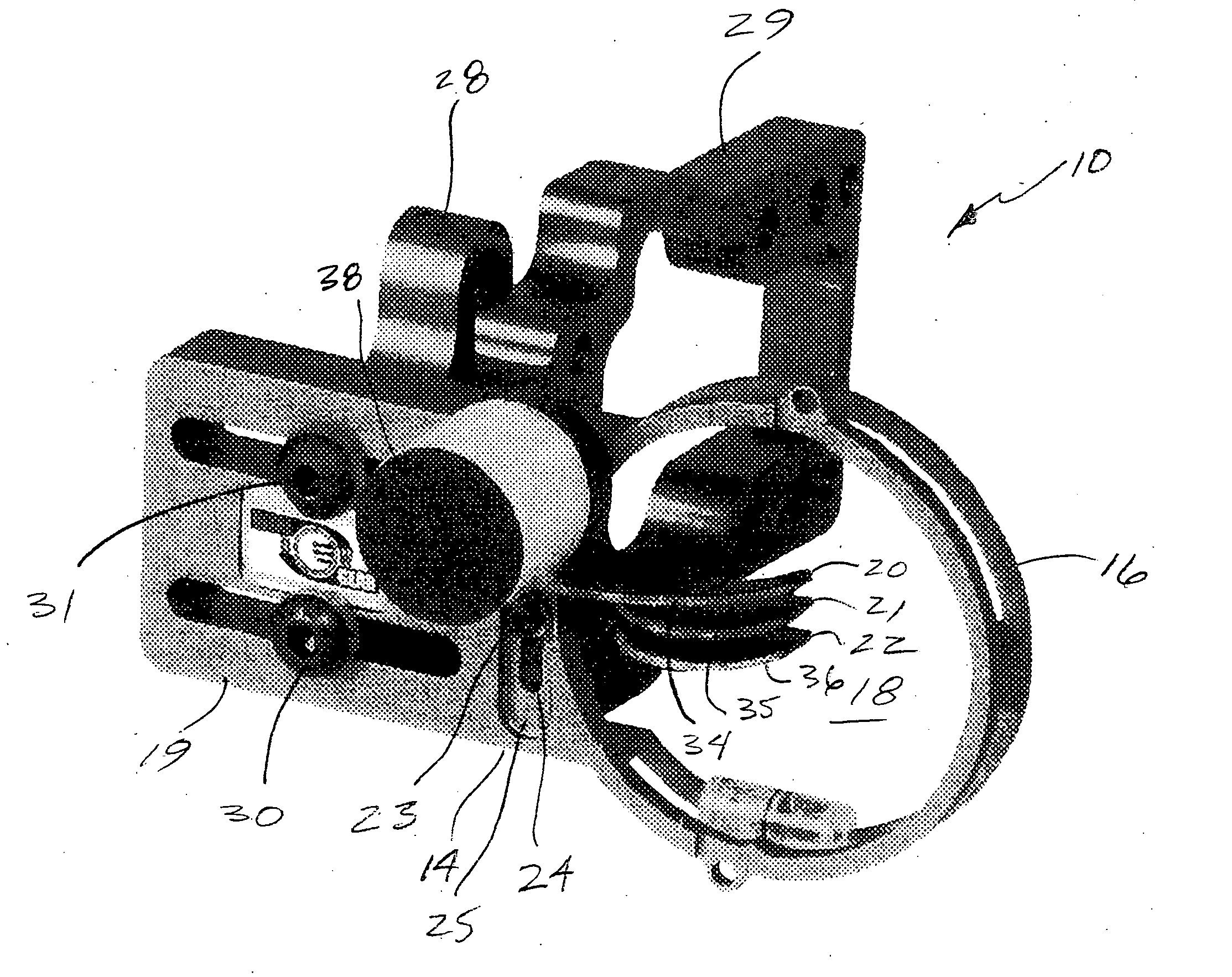
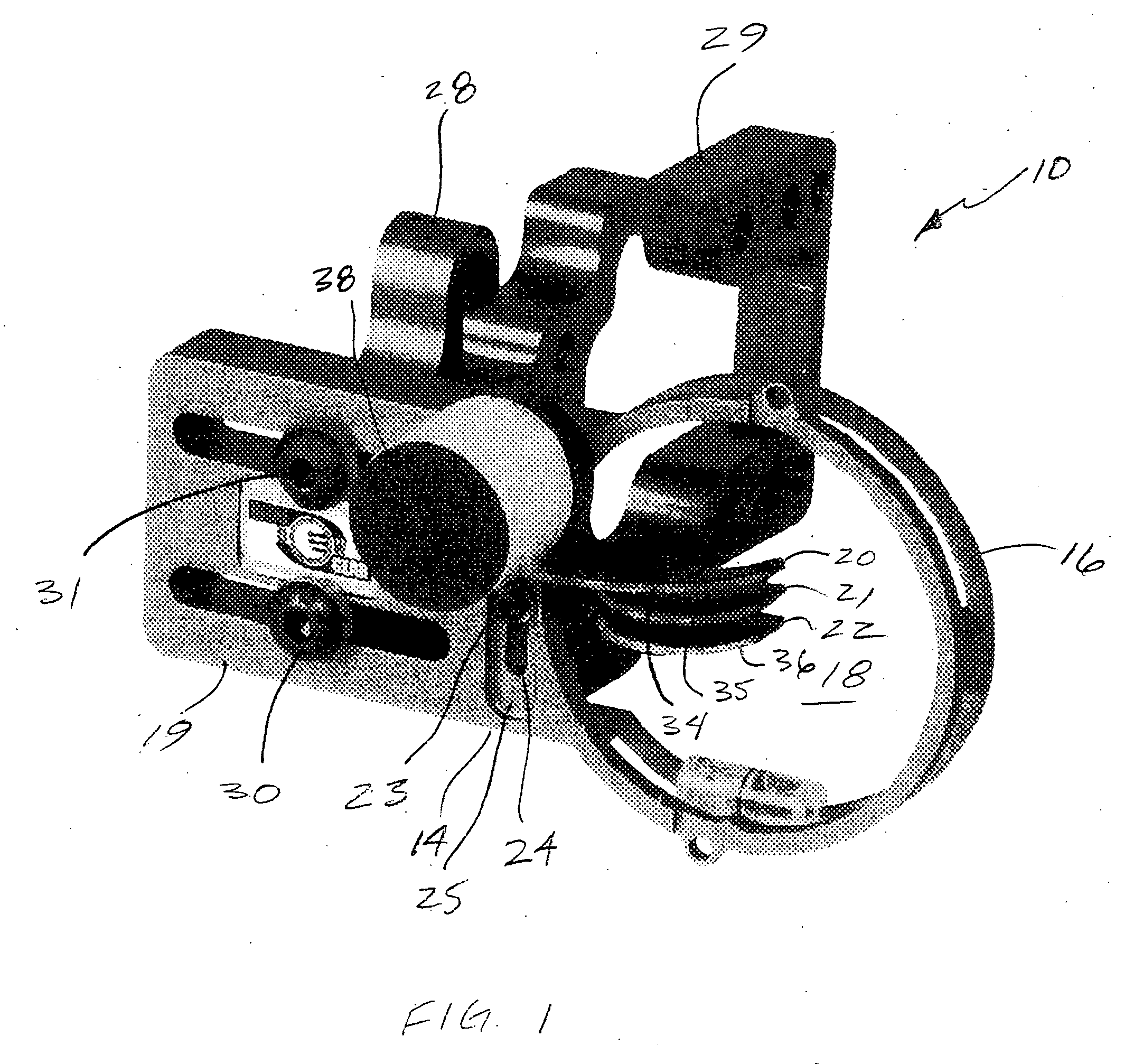
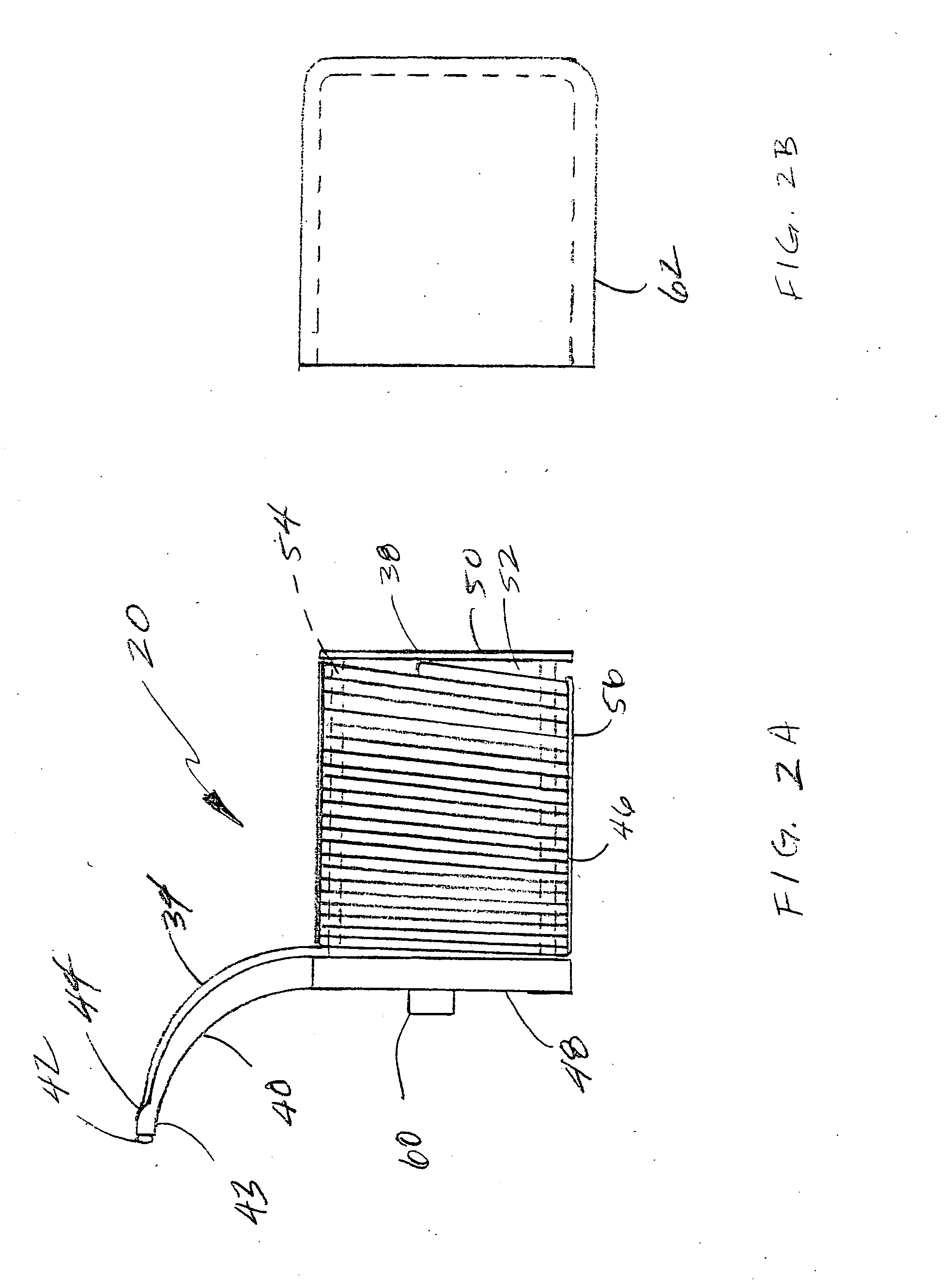
[0037]FIG. 1 illustrates a bow sight device, generally indicated at 10 in accordance with the principles of the present invention. The sighting device 10 is comprised of an integrated pin plate 14, a pin guard 16, which defines a sight window 18, and a mounting portion 19. A plurality of sight pins 20, 21 and 22 are secured to the pin plate 14 by attachment members 23, such as screws, each of which engage one of the sight pins 20, 21 and 22 and extend through a slot 24 formed in the pin plate 14. The sight pin 20 includes an elongate segment of fiber optic material 34 used to form a sighting indicia at one of its terminal ends. The other end of the fiber optic member 34 is wound upon a spool 38 to increase the exposed surface area of the fiber optic material 34 to increase light absorption and thus the brightness of the sight indicia.

[0038] The slot 24 is provided with a recessed portion 25 that circumscribes an elongate channel that extends through the pin plate 14. As will be descri


PUM


Abstract

A sight pin for use with a bow sight includes an elongate segment of fiber optic material used to form a sighting indicia at one of its terminal ends. The other end of the fiber optic member is wound upon a spool to increase the exposed surface area of the fiber optic material to increase light absorption and thus the brightness of the sight indicia.

Description


Claims


Application Information

Patent Timeline
Owner AFSHARI ABBAS BEN
Why Eureka
Try Eureka