Dust scrubber

Inactive Publication Date: 2005-12-08
JOHNSON LESLIE VINCENT PEDDLE
View PDF10 Cites 15 Cited by
  • Summary
  • Abstract
  • Description
  • Claims
  • Application Information

AI Technical Summary

Benefits of technology

[0017] the water removal means positioned in the housing parallel to the direction of air flow thereby potentially allowing for increasing the surface area of the water removal means along a length of the housing as opposed to a position oblique to the air flow wherein the size of the water removal means is limited by a cross sectional dimension or area of the housing wherein the parallel position by presenting a minimal drag profile to the air flow, and increased surface area reduces the air pressure and velocity required to remove dust for a given volume of air and, wherein in use, the energy consumption of the cyclonic vacuum means is thereby also reduced.
[0018] Furthermore, the parallel position of the water removal means or demister allows the air to stabilise and homogenise which reduces the load on the demister by eliminating surges in air flow and constituents, namely dust and water particles. This in addition, eliminates the requirement of additional means downstream of the demister, such as vanes or similar devices which are required for augmenting the removal of the water droplets during overload conditions or continuous heavy duty operation.

Problems solved by technology

In particular, the problems associated with inhalation of mineral dust in mining operations contribute, for example, to certain medical conditions such as asbestosis, silicosis, industrial asthma and mesothelioma.
The contraction of such debilitating diseases is an occupational hazard for workers or miners in the mineral refining industries and the cost to the community is very high in insurance premiums and payouts.
Such equipment requires high energy to operate as contaminated air is inducted at high velocity and pressure into the scrubbing vessel wherein it is passed through a fine mist of water.
As there is high resistance to air flow, movement of the air through the prior art scrubbers require large motor driven fans that correspondingly consume large amounts of energy in the form of electricity or diesel fuel.
There is also the problem of high noise generation levels with the use of large fans and motors.

Method used


Image

  • Dust scrubber
  • Dust scrubber
  • Dust scrubber

Examples


Example

Example 1

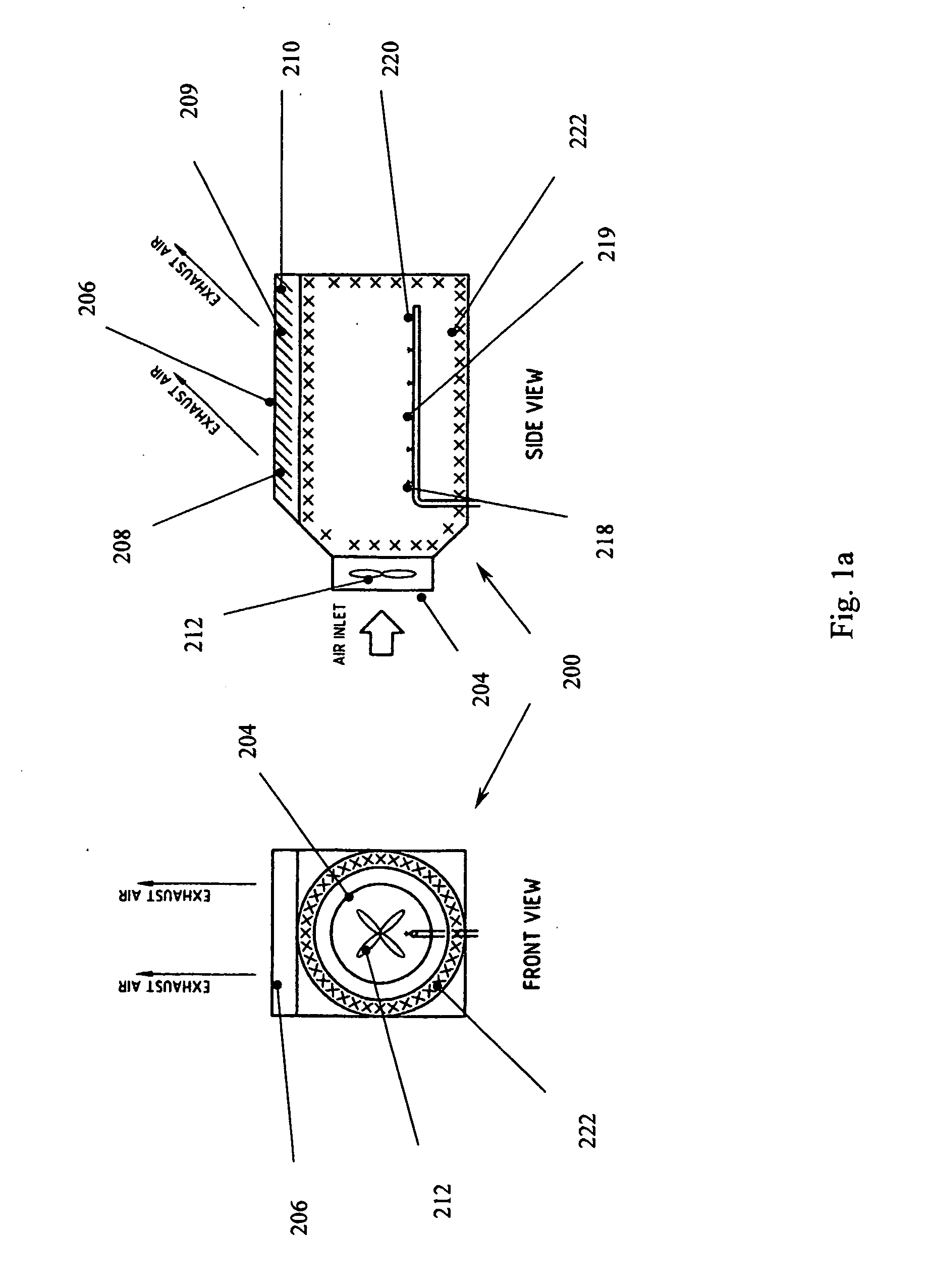
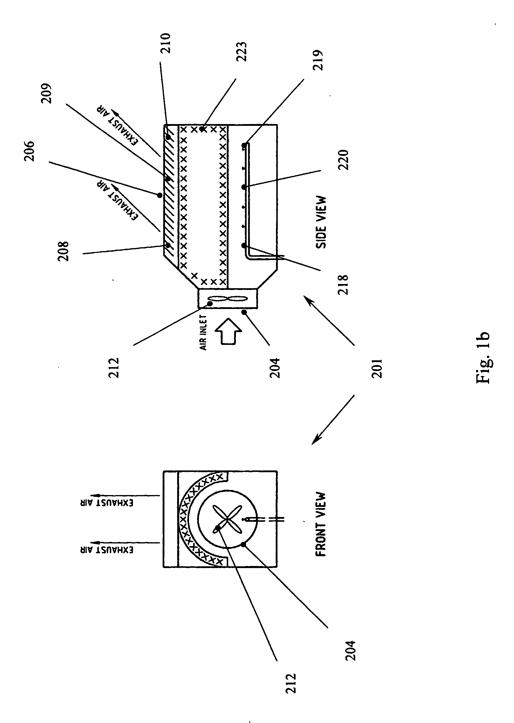
[0039]FIGS. 1a and 1b show preferred embodiments of the invention according to Example 1. The wet dust removal apparatus 200, shown in front and side views, 201 respectively comprises a rectangular housing of stainless steel. The housing has an inlet 204 and an outlet 206 wherein the outlet preferably has directional vane members 208-210 to direct the outflow of clean air in a preferred direction. The inlet houses a multi bladed fan 212 and comprises the air induction means which is powered preferably by an electrical hydraulic motor. The use of hydraulic motors is preferred in mining applications, as there is a danger of arcing or sparking with electric motors. Air containing dust particles are induced by the fan to flow into the housing via the inlet. Water mist is then sprayed into the air stream by a plurality of nozzles 218, 219, 220 comprising the water spraying means. Droplets of water capturing the dust particles are removed by the mist eliminator 222, 223. The mist e

Example

Example 2

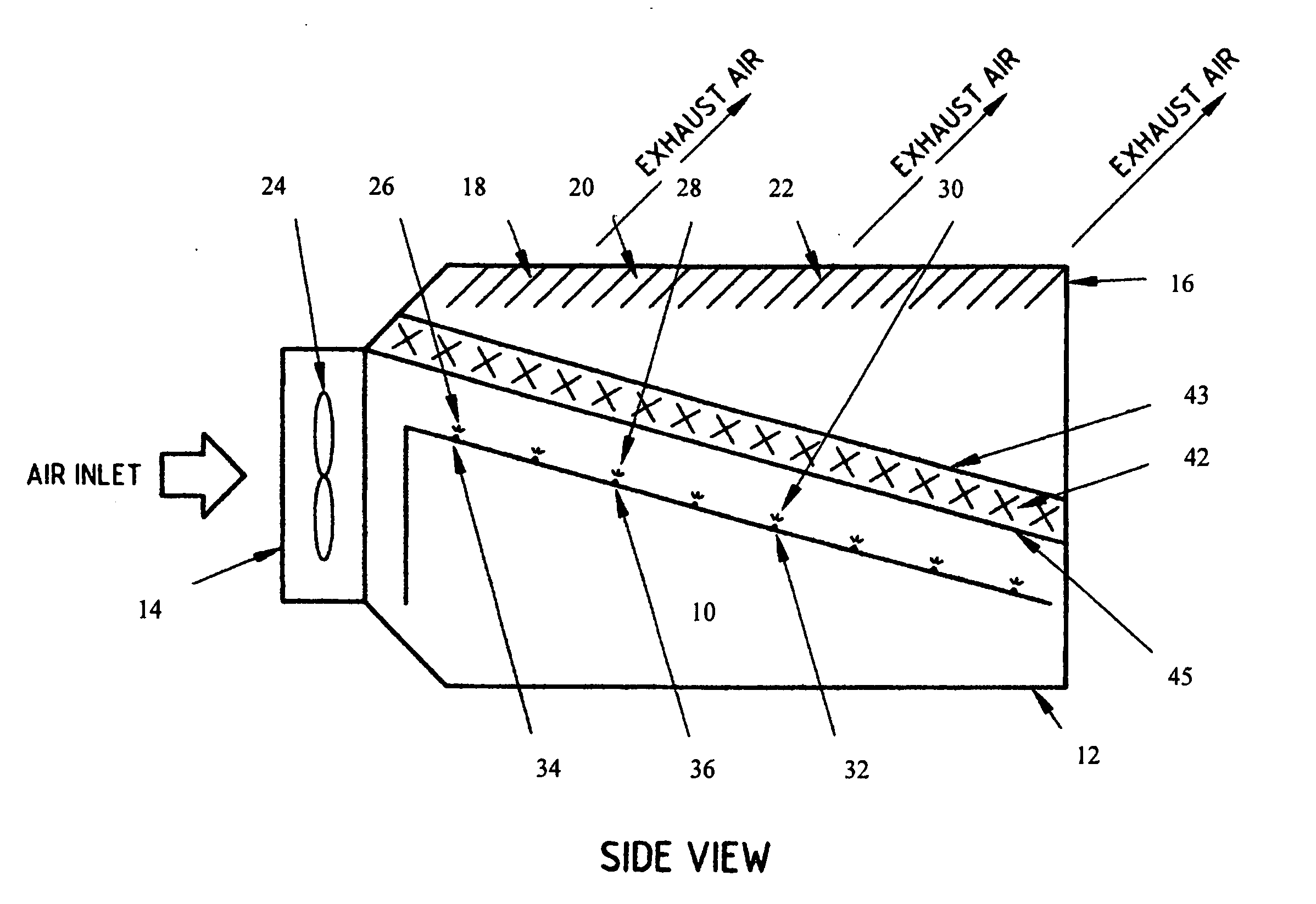
[0044]FIG. 3 shows a preferred embodiment of the second aspect of the invention according to Example 2. In this example, the wet and dry dust removal apparatus is especially adapted for use with drilling applications. The apparatus 110 is shown having a cylindrical housing 112 with an inlet 114 into which air containing large and small particulate material from around a drill from powered air induction means similar to that described in Example 1 is introduced. The cyclonic vacuum means 116 preferably comprises an electric motor driven cyclone type vessel 118 which is adapted to remove particles larger than 1.0 mm in size by centrifugal action. Smaller particles that do not conform to the physical forces required for removal by the centrifugal action pass from the cyclone type vessel into a mist 120, 122 produced by the nozzles 123, 124 of the water spraying means. The smaller particles of dust are caught by the water droplets which are then trapped by the mist eliminator 126


PUM

PropertyMeasurementUnit
Diameteraaaaaaaaaa
Diameteraaaaaaaaaa
Diameteraaaaaaaaaa

Abstract

A wet and a wet and dry dust removal apparatus, the latter for drilling applications including a housing, adapted to contain powered air induction means to induct air contaminated with particulate matter, water spraying means adapted to spray a mist of water into the induced air stream to capture the particulate matter, water removal means adapted to remove water droplets containing the particulate matter, the water removal means positioned in the housing parallel angle to the direction of the air flow, wherein the paralleled position by presenting a minimal drag profile in the air flow reduces the air pressure and velocity required to remove dust for a given volume of air, so that the energy consumption of the air induction means is correspondingly reduced.

Description


Claims


Application Information

Patent Timeline
Owner JOHNSON LESLIE VINCENT PEDDLE
Why Eureka
Try Eureka