A retaining force adjustable parallel permanent magnetic actuator

A technology of permanent magnet operation and holding force, which is applied in the direction of electromagnetic relay, detailed information of electromagnetic relay, power device inside the switch, etc. To achieve the effect of saving energy consumption, reducing capacity and reducing volume

Inactive Publication Date: 2015-03-11
苏艳刚
View PDF5 Cites 4 Cited by
  • Summary
  • Abstract
  • Description
  • Claims
  • Application Information

AI Technical Summary

Problems solved by technology

However, there are generally two technical defects in the permanent magnet operating mechanism of the distribution switchgear on the market: First, in the design of the magnetic circuit, there is no fundamental solution to the restraining force of the permanent magnetic field on the moving iron core during the opening process of the switchgear. The opening speed can be increased by increasing the reverse spring load or electromagnetic force, with high energy consumption and large control power supply capacity; second, the permanent magnet assembly of the permanent magnet operating mechanism mostly adopts the sealing process of structural glue, and the permanent magnetic field after finalization The generated permanent magnet holding force is too large and cannot be adjusted. It is also necessary to increase the reverse spring load or electromagnetic force to increase the opening speed, increase energy consumption, and increase the capacity of the control power supply. These two technical defects directly affect the power distribution switchgear The performance is also the main factor for the uneven quality of related products on the market

Method used


Image

  • A retaining force adjustable parallel permanent magnetic actuator
  • A retaining force adjustable parallel permanent magnetic actuator
  • A retaining force adjustable parallel permanent magnetic actuator

Examples


Embodiment Construction

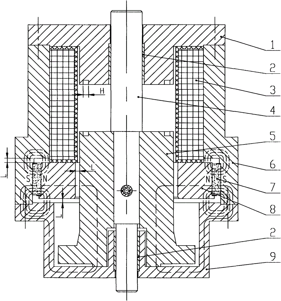
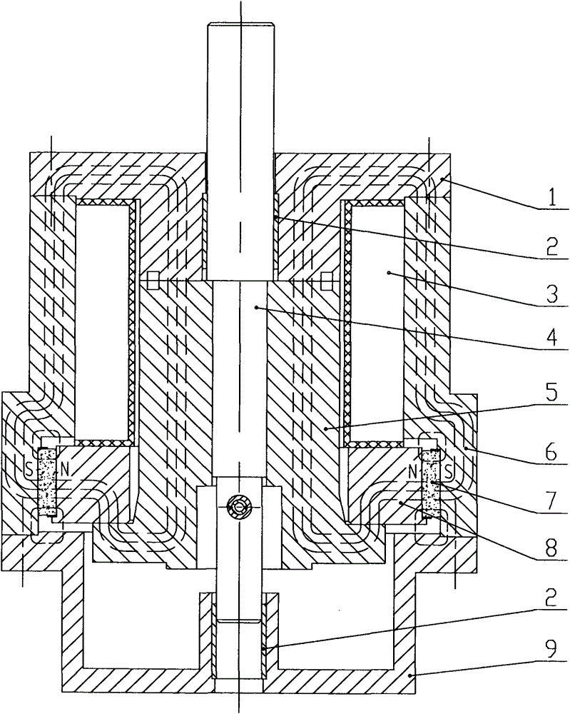
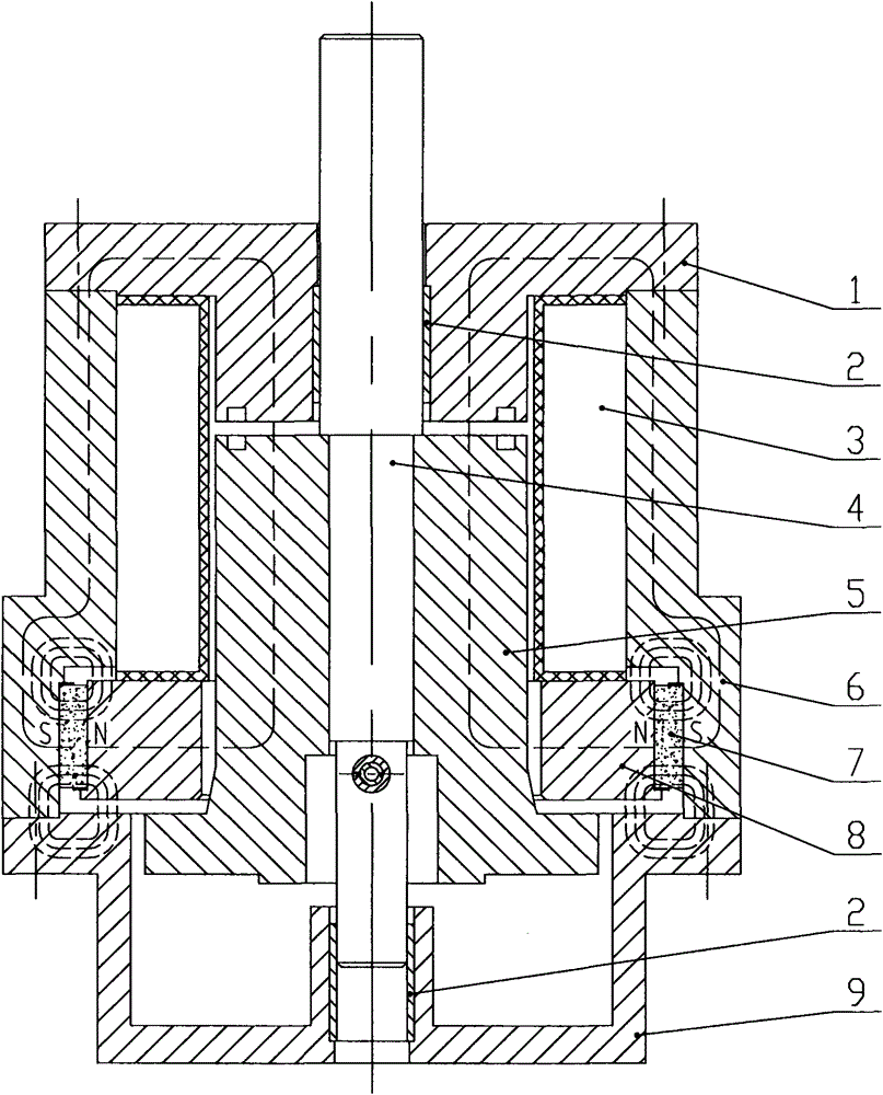
[0015] Such as figure 1 , 2 , 3, the present invention is a parallel magnetic circuit permanent magnet operating mechanism with adjustable holding force, including an upper yoke (1), a self-lubricating bearing (2), a closing and opening coil (3), a push rod ( 4), moving iron core (5), outer magnetic yoke (6), permanent magnet (7), inner magnetic yoke (8) and lower magnetic yoke (9), it is characterized in that: upper magnetic yoke (1) and lower magnetic The center hole of the yoke (9) is respectively embedded with self-lubricating bearings (2), and is fastened on the outer yoke (6) with variable diameter; the permanent magnet (7) has a chamfered inner yoke (8) and The outer yoke (9) is sealed with structural glue; the ejector rod (4) is fixed on the moving iron core (5) with a chamfer and a boss below, and runs through the upper yoke (1) and the lower yoke (9). ); the closing and opening coil (3) is placed in the cavity above the inner yoke (6).

[0016] Wherein there is a ...


PUM


Abstract

The invention discloses a retaining force adjustable parallel permanent magnetic actuator relating to the technical field of a high-voltage electrical apparatus. The retaining force adjustable parallel permanent magnetic actuator includes an upper yoke, self-lubricating bearings, a close-open coil, an ejector pin, a movable iron core, an outer yoke, a permanent magnet, an inner yoke and a lower yoke, and is characterized in that the self-lubricating bearing is embedded to the center hole of each of the upper yoke and the lower yoke, and the upper yoke and the lower yoke are fixed to the reducing outer yoke; the permanent magnet is sealed by a structural adhesive between the outer yoke and the inner yoke which has a chamfer at the lower side; the ejector pin is fixed to the movable iron core having a chamfer and a protrusion at the lower side, and passes through the upper yoke and the lower yoke; and the close-open coil is positioned in an upper cavity of the inner yoke. The close-open speed is improved by the formation of two parallel magnetic paths with the main magnetic path, and the formation of a groove on a face where the upper yoke attracts the movable iron core, and also the energy consumption is reduced and the capacity of the control power supply is reduced. The invention plays a role of improving reliability of the switching device and promoting energy conservation.

Description

technical field [0001] The invention relates to a parallel magnetic circuit permanent magnet operating mechanism with adjustable holding force for distribution and consumption switchgear, belonging to the technical field of high-voltage electrical appliances. Background technique [0002] With the continuous development of the national smart grid construction, the permanent magnet operating mechanism has been widely used in power distribution switchgear by virtue of its advantages in power electronic control and reliability in transmission. However, there are generally two technical defects in the permanent magnet operating mechanism of the distribution switchgear on the market: First, in the design of the magnetic circuit, there is no fundamental solution to the restraining force of the permanent magnetic field on the moving iron core during the opening process of the switchgear. The opening speed can be increased by increasing the reverse spring load or electromagnetic for...

Claims


Application Information

Patent Timeline
IPC IPC(8): H01H3/28
CPCH01H50/40H01H50/18H01H51/01
Inventor 苏艳刚
Owner 苏艳刚
Why Eureka
Try Eureka