Fluorescent image-printed article and fluorescent ink
a technology of fluorescent ink and image, applied in the field of fluorescent image printed articles, can solve the problems of insufficiently solving the problem of deterioration of security level, and achieve the effect of improving the security level of articles
- Summary
- Abstract
- Description
- Claims
- Application Information
AI Technical Summary
Benefits of technology
Problems solved by technology
Method used
Image

Examples
example 1
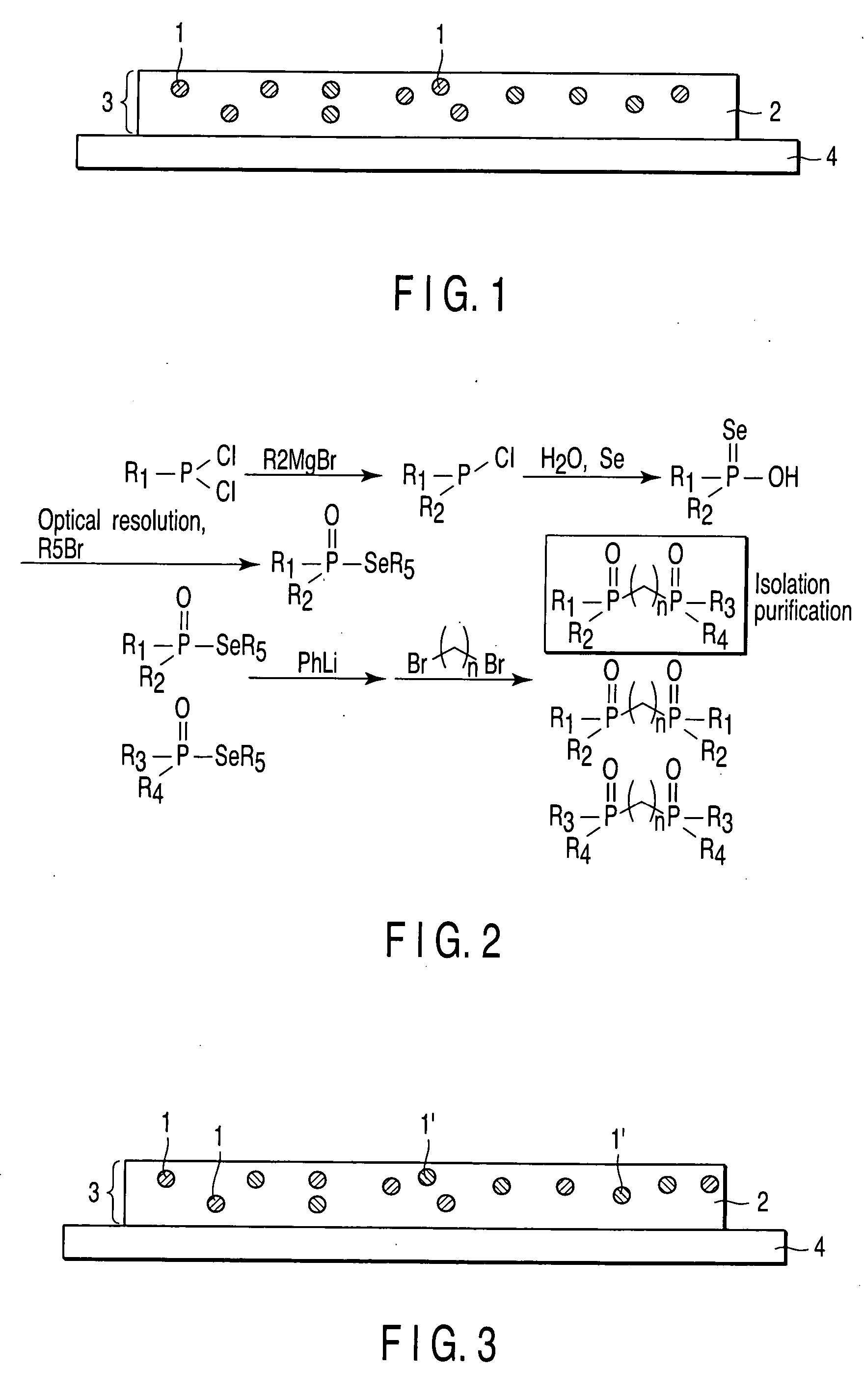
[0112] According to the following reaction formula (5), a rare earth complex was synthesized. Namely, as a ligand, two kinds of phosphine oxide, i.e. triphenyl phosphine oxide and trioctyl phosphine oxide are reacted with a rare earth metal compound to obtain a rare earth complex. This rare earth complex was then dissolved in Bartrel XF (fluorine-contained solvent; Du Pont Co., Ltd.) to obtain a solution. To this solution was further added 2% by weight of pellets of Dainion THV (one of fluorine-contained polymers represented by the following formula (6); Simitomo 3M Co., Ltd.) to obtain a solution (ink). The solution (ink) prepared in this manner was then coated on a glass substrate by means of spin-coating to form a layer, thereby obtaining a fluorescent image-printed article.
[0113] (wherein, q and r are respectively an integer; and Rf1 and Rf2 are individually a linear or branched alkyl group having not more than 20 carbon atoms and having in its molecule structure at least one flu
example 2
[0119] A rare earth complex was synthesized by following the same procedures as described in Example 1 except that diphosphine dioxide having a structure represented by the following formula (7) was substituted for the phosphine oxide employed as a ligand in the reaction formula (5). Then, by making use of this rare earth complex, an ink and a fluorescent image-printed article were manufactured in the same manner as described in Example 1.
[0120] In the same manner as in the case of Example 1, the emission and transparency of the image of this fluorescent image-printed article were measured. When black light and light from an LED having a central wavelength of 410 nm were irradiated to this fluorescent image-printed article, a strong red emission was recognized. This image could not be visually observed unless these lights were irradiated, thus obtaining a fluorescent image-printed article excellent in security.
example 3
[0121] A rare earth complex was synthesized by following the same procedures as described in Example 1 except that diphosphine dioxide having a structure represented by the following formula (8) was substituted for the phosphine oxide employed as a ligand in the reaction formula (5). Then, by making use of this rare earth complex, an ink and a fluorescent image-printed article were manufactured in the same manner as described in Example 1.
[0122] In the same manner as in the case of Example 1, the emission and transparency of the image of this fluorescent image-printed article were measured. When black light and light from an LED having a central wavelength of 410 nm were irradiated to this fluorescent image-printed article, a strong red emission was recognized. This image could not be visually observed unless these lights were irradiated, thus obtaining a fluorescent image-printed article excellent in security.
PUM
| Property | Measurement | Unit |
|---|---|---|
| Fluorescence | aaaaa | aaaaa |
Abstract
Description
Claims
Application Information
 - R&D Engineer
- R&D Manager
- IP Professional
- Industry Leading Data Capabilities
- Powerful AI technology
- Patent DNA Extraction
Browse by: Latest US Patents, China's latest patents, Technical Efficacy Thesaurus, Application Domain, Technology Topic.
© 2024 PatSnap. All rights reserved.Legal|Privacy policy|Modern Slavery Act Transparency Statement|Sitemap