Method for operating an internal combustion engine and device for executing the method

a technology of internal combustion engine and method, which is applied in the direction of machines/engines, lighting and heating apparatus, separation processes, etc., can solve the problems of unpurified exhaust gas reaching the environment, reducing the performance capability of scr catalytic converter, etc., and achieves the effect of increasing the reliability during the operation of the internal combustion engine and being easily flammabl

Inactive Publication Date: 2006-09-07
ROBERT BOSCH GMBH
View PDF4 Cites 16 Cited by
  • Summary
  • Abstract
  • Description
  • Claims
  • Application Information

AI Technical Summary

Benefits of technology

It describes an improved way to test the performance of certain components within an automobile's emission control system by measuring their pressurized levels with different types of agents like fuels (fuel) and compressed gases. By comparing these measurements against predetermined thresholds, any issues can quickly identified without having to stop working altogether. Additionally, this approach helps maintain proper functioning of the component due to its ability to resist being damaged from excessive temperatures over long periods of usage.

Problems solved by technology

This patented technical problem addressed in this patents relates to improving diesel engines' efficiency through selectively controlling certain chemical substances called ureasulfonamydrins ("UAS") within specific concentrations while minimizing harmful effects caused by these compounds.

Method used


Image

  • Method for operating an internal combustion engine and device for executing the method
  • Method for operating an internal combustion engine and device for executing the method
  • Method for operating an internal combustion engine and device for executing the method

Examples


Embodiment Construction

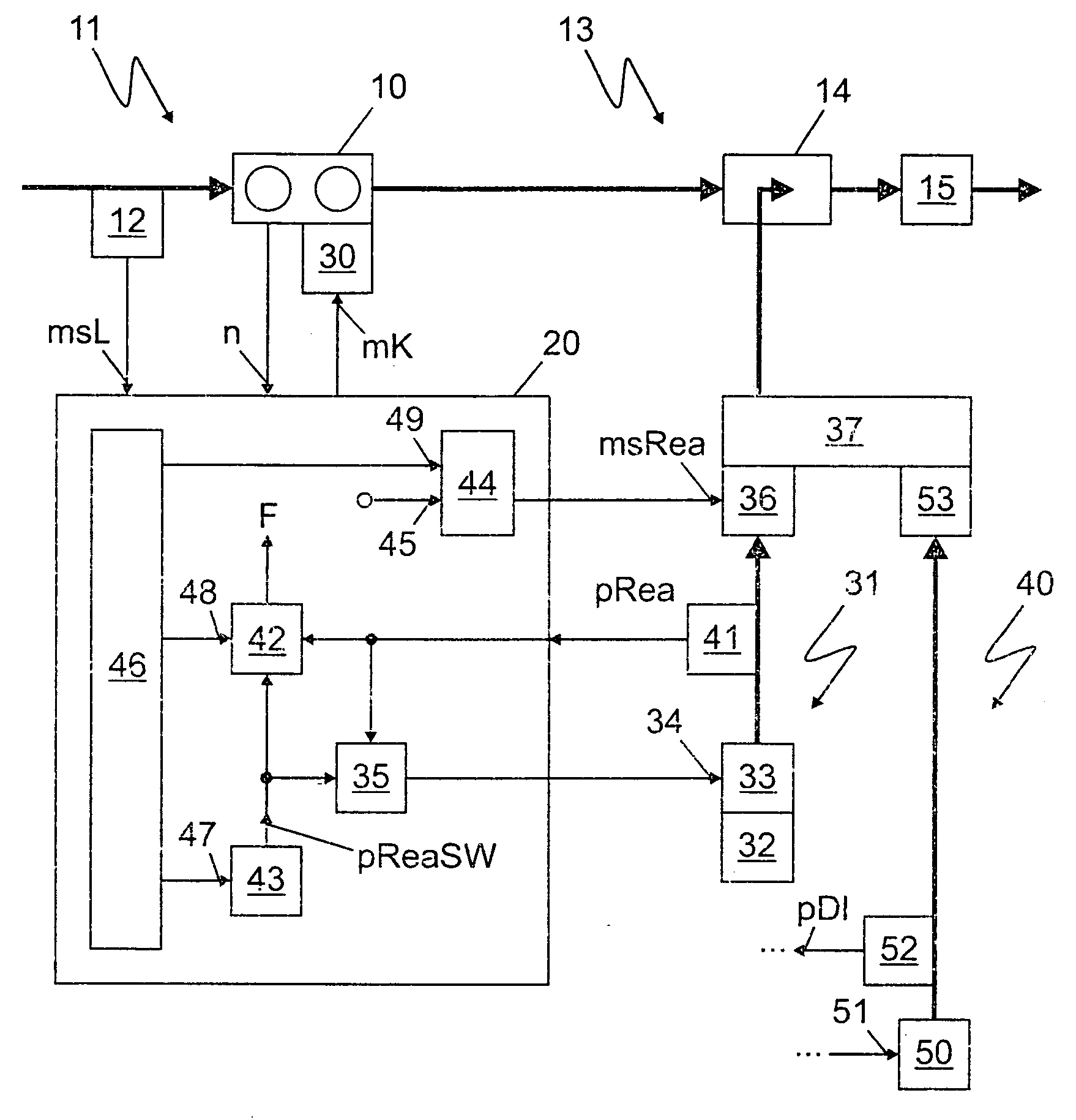
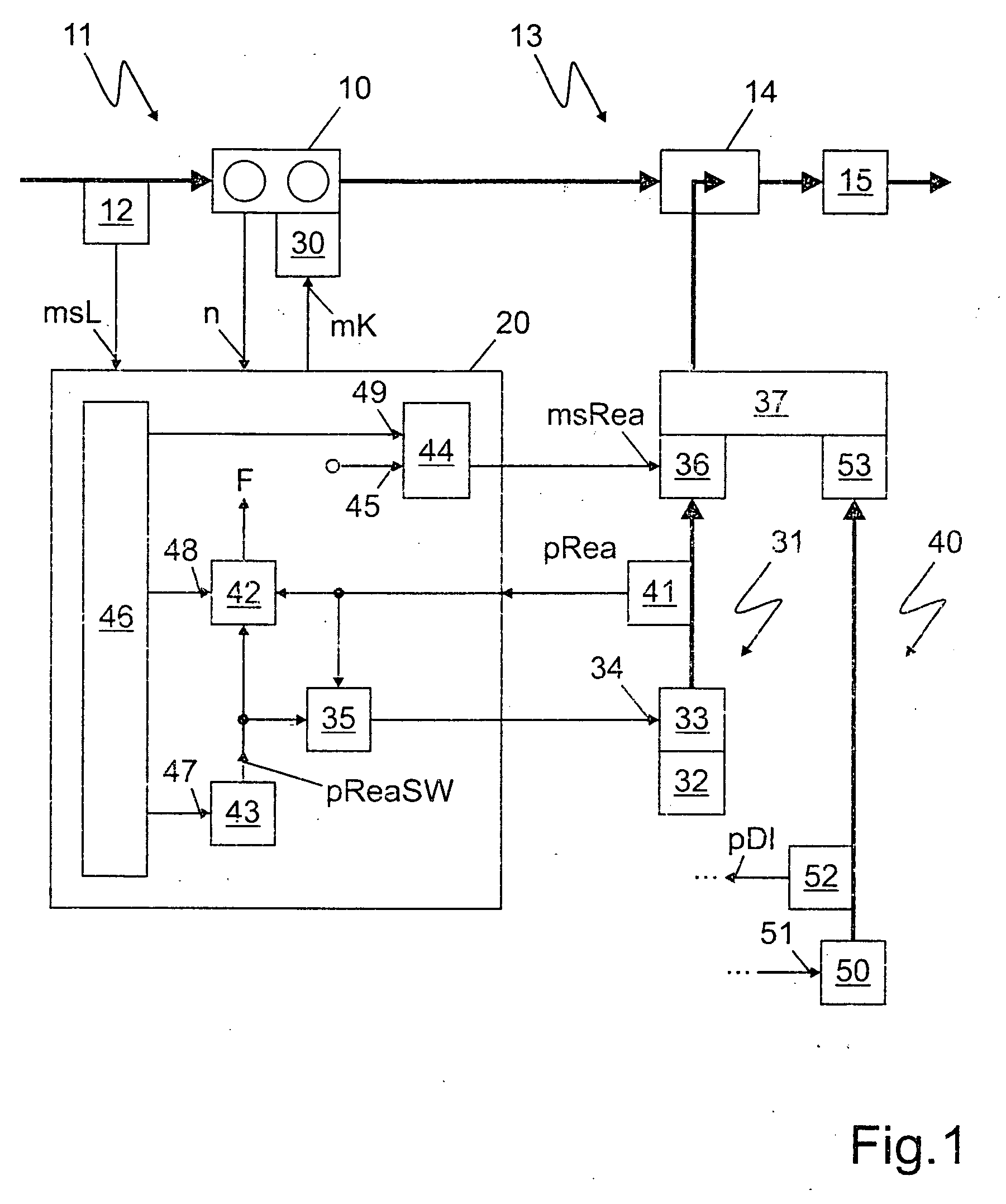
[0020]FIG. 1 shows an internal combustion engine 10, in whose intake area 11 an intake air detector 12 is positioned and in whose exhaust gas system 13 a reagent introduction device 14 and an exhaust gas treatment device 15 are positioned.

[0021] Intake air detector 12 outputs an air signal msL to a control unit 20 and internal combustion engine 10 outputs a speed n to control unit 20.

[0022] Control unit 20 provides a fuel signal mK to a fuel metering device 30.

[0023] In a reagent path 31, a reagent stored in a reagent tank 32 is brought to a predefined reagent setpoint pressure pReaSW by a reagent pump 33. Reagent pump 33 is activated by a reagent pump activation signal 34, which is provided by a reagent pump activator 35 positioned in control unit 20.

[0024] The reagent reaches a reagent dosing valve 36, which is connected to a mixing chamber 37. Furthermore, mixing chamber 37 is connected to a compressed air path 40. After mixing chamber 37, the reagent reaches reagent introductio


PUM

PropertyMeasurementUnit
Pressureaaaaaaaaaa
Threshold limitaaaaaaaaaa

Abstract

A method for operating an internal combustion engine, in whose exhaust gas system an exhaust gas treatment device is positioned, a reagent, which is possibly mixed with compressed air, being introduced into the exhaust gas system upstream from the exhaust gas treatment device, and a device for performing the method. The reagent is brought to a predefined reagent setpoint pressure using a reagent pump and subsequently metered using a reagent dosing valve. The reagent pressure existing upstream from the reagent dosing valve is detected. In the framework of a diagnosis, a time curve of the reagent setpoint pressure is predefined. The reagent pressure detected during the diagnosis is compared to at least one predefined threshold value. If the threshold value is exceeded, an error signal is provided. The corresponding diagnosis of a compressed air path may be provided alternatively or additionally to the diagnosis of the reagent path.

Description


Claims


Application Information

Patent Timeline
Owner ROBERT BOSCH GMBH
Why Eureka
Try Eureka