Method and apparatus for adjustment of synchronous clock signals

a clock signal and synchronization clock technology, applied in the direction of digital transmission, synchronisation information channel, synchronisation signal speed/phase control, etc., can solve the problems of synchronisation clock signal misalignment, loss of information carried in data signal, clock signal misalignment with data signal, etc., to achieve the effect of increasing the delay of synchronisation clock signal

Active Publication Date: 2007-05-03
TERADYNE
View PDF21 Cites 1 Cited by
  • Summary
  • Abstract
  • Description
  • Claims
  • Application Information

AI Technical Summary

Benefits of technology

This patent describes a way to calibrate a timing system that uses a sync-synchronous clock signal. By gradually increasing or reducing its time between two different times during this process, it becomes easier to adjust the timing accurately.

Problems solved by technology

The technical problem addressed in this patent text is how to ensure proper timing between different sources of time (clock) in order to achieve efficient communication within an electronic testing system or other equipment.

Method used


Image

  • Method and apparatus for adjustment of synchronous clock signals
  • Method and apparatus for adjustment of synchronous clock signals
  • Method and apparatus for adjustment of synchronous clock signals

Examples


Embodiment Construction

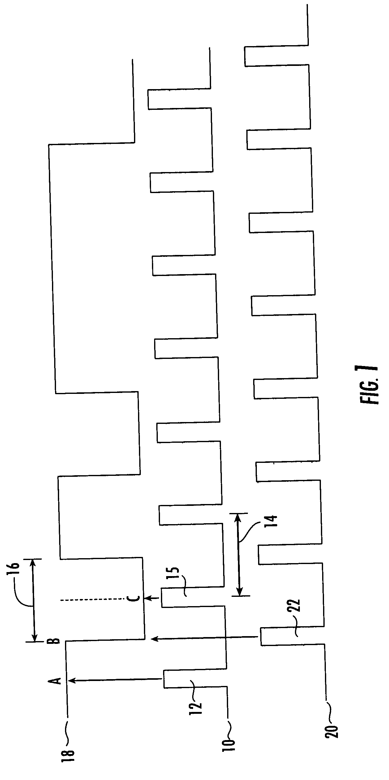
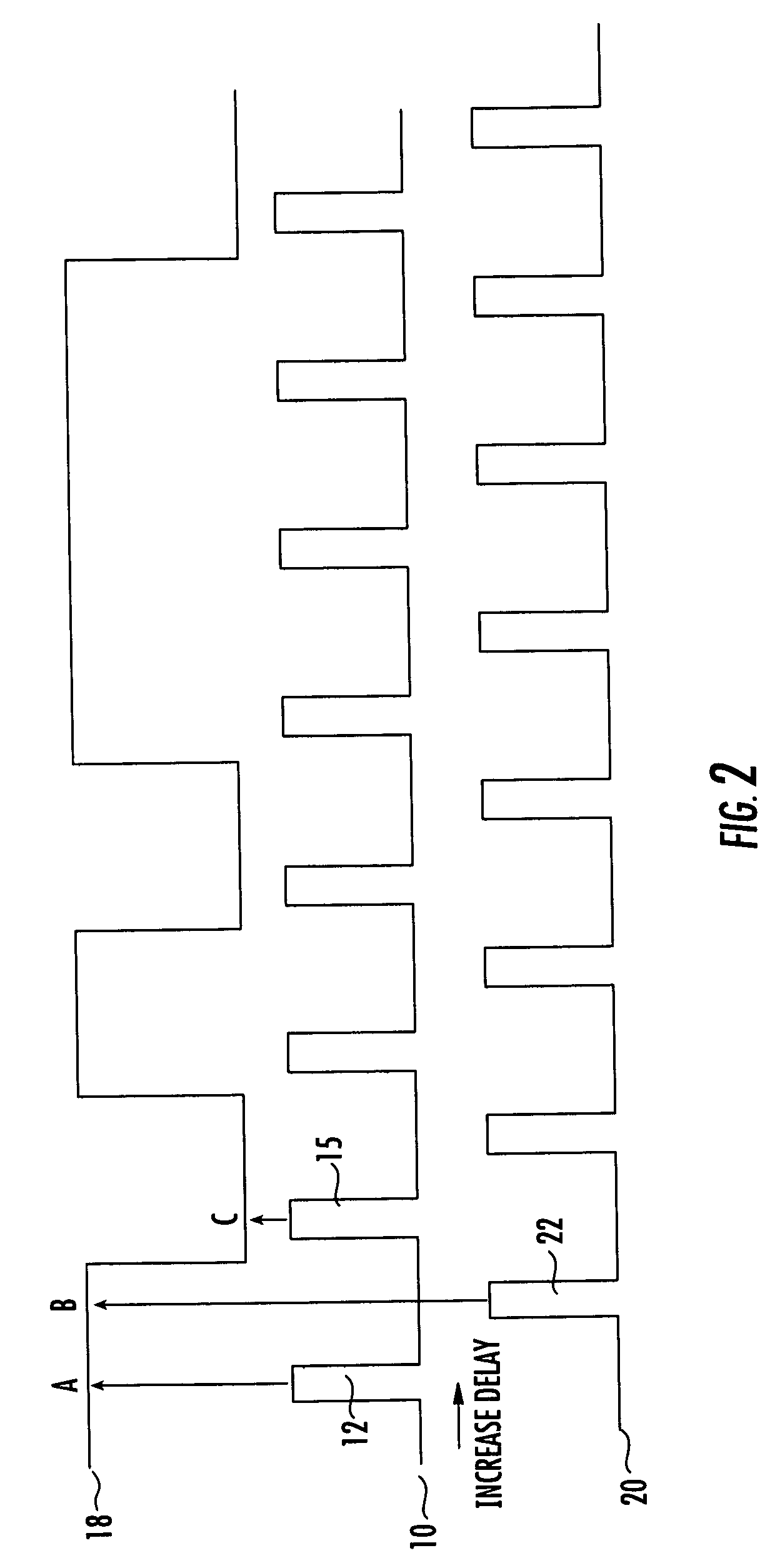
[0014] Illustrative embodiments of the present invention are described with reference to data signals, synchronous clock signals and offset clock signals. Timing diagrams showing the relative timing of a data signal, a synchronous clock signal and offset clock signal are presented in FIGS. 1-3. Referring to FIG. 1, a synchronous clock signal 10 includes a train of synchronous clock pulses 12 that can have a period 14 corresponding to a data cycle 16 of a data signal 18. An offset clock signal 20 includes a train of offset clock pulses 22 that have the same period 14 as the synchronous clock signal but are offset from the synchronous clock pulses 12 by one half period (e.g., one half of data cycle 16). The signals shown in FIG. 1 represent ideal timing wherein the synchronous clock pulses 12 should occur at the center of each data cycle 16 (e.g., at time A). In the ideal representation shown in FIG. 1, any transition of the data signal 18 should occur simultaneously with an offset clock


PUM


Abstract

A synchronous clock signal can be adjusted relative to a data signal by decreasing a delay in the synchronous clock signal if a transition of a data signal occurs before a pulse of an offset clock signal which is delayed by one half cycle relative to the synchronous clock signal. The synchronous clock signal can be delayed if the transition of the data signal occurs after the pulse of the offset synchronous clock signal.

Description


Claims


Application Information

Patent Timeline
Owner TERADYNE
Why Eureka
Try Eureka