Electric rolling stock driving apparatus
a technology of electric rolling stock and driving apparatus, which is applied in the direction of electric devices, locomotives, transportation and packaging, etc., can solve the problems of complicated wiring and piping, and achieve the effects of improving the reliability of the rolling stock system, increasing the trouble restoration time, and increasing the manufacturing term of the rolling stock
- Summary
- Abstract
- Description
- Claims
- Application Information
AI Technical Summary
Benefits of technology
Problems solved by technology
Method used
Image


Examples
first embodiment
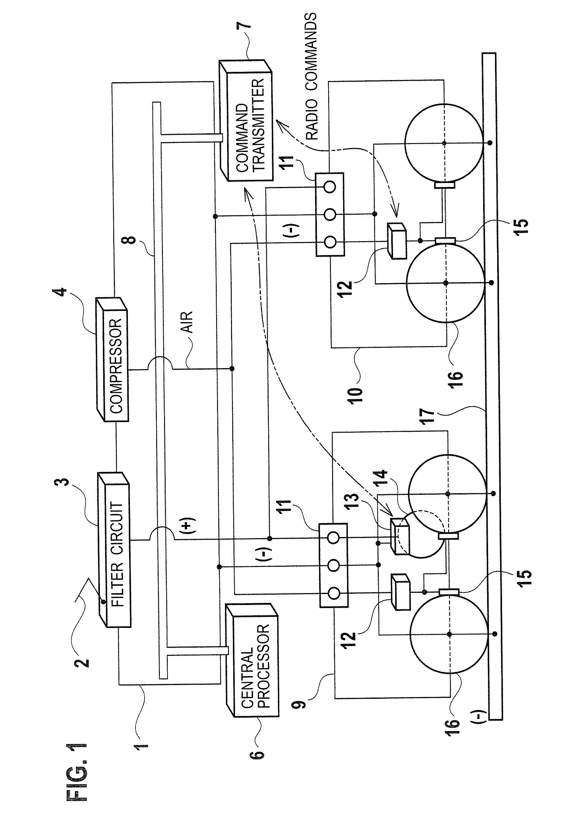
[0015]Description is now made of an electric rolling stock driving apparatus according to the first embodiment of the invention, with reference to FIG. 1. In a dc (direct current) electric rolling stock, a car body 1 is mounted on a driving truck 9 and a trailing truck 10. The car body 1 has a pantograph 2, an LC filter circuit 3, and a compressor 4 for services of compressed air, supported on a roof thereof. Further, in the car body 1, a central processor 6 and a command transmitter 7 with a function of radio communications are installed, which are interconnected by an intra-vehicle LAN 8.
[0016]The driving truck 9 is provided with a main motor 14 for driving a set of wheels 16 to rotate as drive wheels, a VVVF inverter 13 for driving the main motor 14 in a controlling manner, and a brake controller 12 adapted for control of braking forces of brake shoes 15 acting on the wheels 16. On the other hand, the trailing truck 10 is simply provided with a brake controller 12. The command trans
second embodiment
[0027]Description is now made of an electric rolling stock driving apparatus according to the second embodiment of the present invention, with reference to FIG. 2. Relative to the first embodiment shown in FIG. 1, the present embodiment features a driving truck 9 provided in place of the trailing truck 10, thus having a pair of driving trucks 9 provided for a car body 1, a DC / DC (dc-to-dc) converter 18 additionally provided on a roof of the car body 1. In FIG. 2, like elements to the first embodiment of FIG. 1 are designated by like reference characters.
[0028]The paired driving trucks 9 have a power supply as a common circuit, which is composed of an LC filter circuit 3 and a DC / DC converter 18. The DC / DC converter 18 serves to boost or drop a dc output voltage of the LC filter circuit 3.
[0029]According to the present embodiment, a plurality of driving trucks 9 have their VVVF inverters 13 installed therein, which do not have their dc power supply input circuits as equipments sep
third embodiment
[0030]Description is now made of an electric rolling stock driving apparatus according to the third embodiment of the present invention, with reference to FIG. 3. Relative to the first embodiment shown in FIG. 1, the present embodiment features an energy accumulator 19 (as an energy storage device) provided under a floor of a car body 1. The energy accumulator 19 is adapted for charge and discharge of a large capacity of energy, and may comprise, for example, an EDLC (electric double-layer capacitor), a secondary cell, a fuel cell, or a diesel engine. Other elements of the third embodiment shown in FIG. 3 are common to the first embodiment shown in FIG. 1.
[0031]According to the present embodiment, a combination of a brake controller 12 and a VVVF inverter 13, to be disposed under a floor of a car body 1 in a relevant art, are installed together with a main motor 14 inside the driving truck 9, thus having a large space secured under a floor of the car body 1. There have been proposed va
PUM
 Abstract
Description
Claims
Application Information
 - R&D Engineer
- R&D Manager
- IP Professional
- Industry Leading Data Capabilities
- Powerful AI technology
- Patent DNA Extraction
Browse by: Latest US Patents, China's latest patents, Technical Efficacy Thesaurus, Application Domain, Technology Topic.
© 2024 PatSnap. All rights reserved.Legal|Privacy policy|Modern Slavery Act Transparency Statement|Sitemap