Method to make and use long single-walled carbon nanotubes as electrical conductors

a single-walled carbon nanotube, long-diameter technology, applied in the direction of catalyst activation/preparation, metal/metal-oxide/metal-hydroxide catalyst, physical/chemical process catalyst, etc., can solve the problem of less efficient process, achieve enhanced environment for ultra-long nanotube formation, reduce turbulence, and reduce turbulence

Active Publication Date: 2008-01-24
RGT UNIV OF CALIFORNIA
View PDF13 Cites 5 Cited by
  • Summary
  • Abstract
  • Description
  • Claims
  • Application Information

AI Technical Summary

Benefits of technology

There are many ways that make it easier than ever before we start growing very small carbon tubules with tiny holes called nanoconductors (CNC). These techniques involve adding certain chemical substances or gases into a reactor containing a catalyst at high temperatures. By controllably increasing temperature over time, these materials form smaller carbon structures known as “nanostructures” inside each tube. However, this method requires fast coolings but also increases turbulences within the process due to the presence of other components such as metals used along its way through the production line. To reduce these issues, there has been developed a new type of device called a lift off machine (LMO) that helps free up space between two layers of material when they shouldn't get too much weight.

Problems solved by technology

This patented technical problem addressed in this patents relates to efficiently producing very thin layers of highly purified nanoparticles made through various techniques involving different types of reactants. Existing systems involve multiple steps and may result in contamination issues due to residual particles left behind after each step.

Method used


Image

  • Method to make and use long single-walled carbon nanotubes as electrical conductors
  • Method to make and use long single-walled carbon nanotubes as electrical conductors
  • Method to make and use long single-walled carbon nanotubes as electrical conductors

Examples


Embodiment Construction

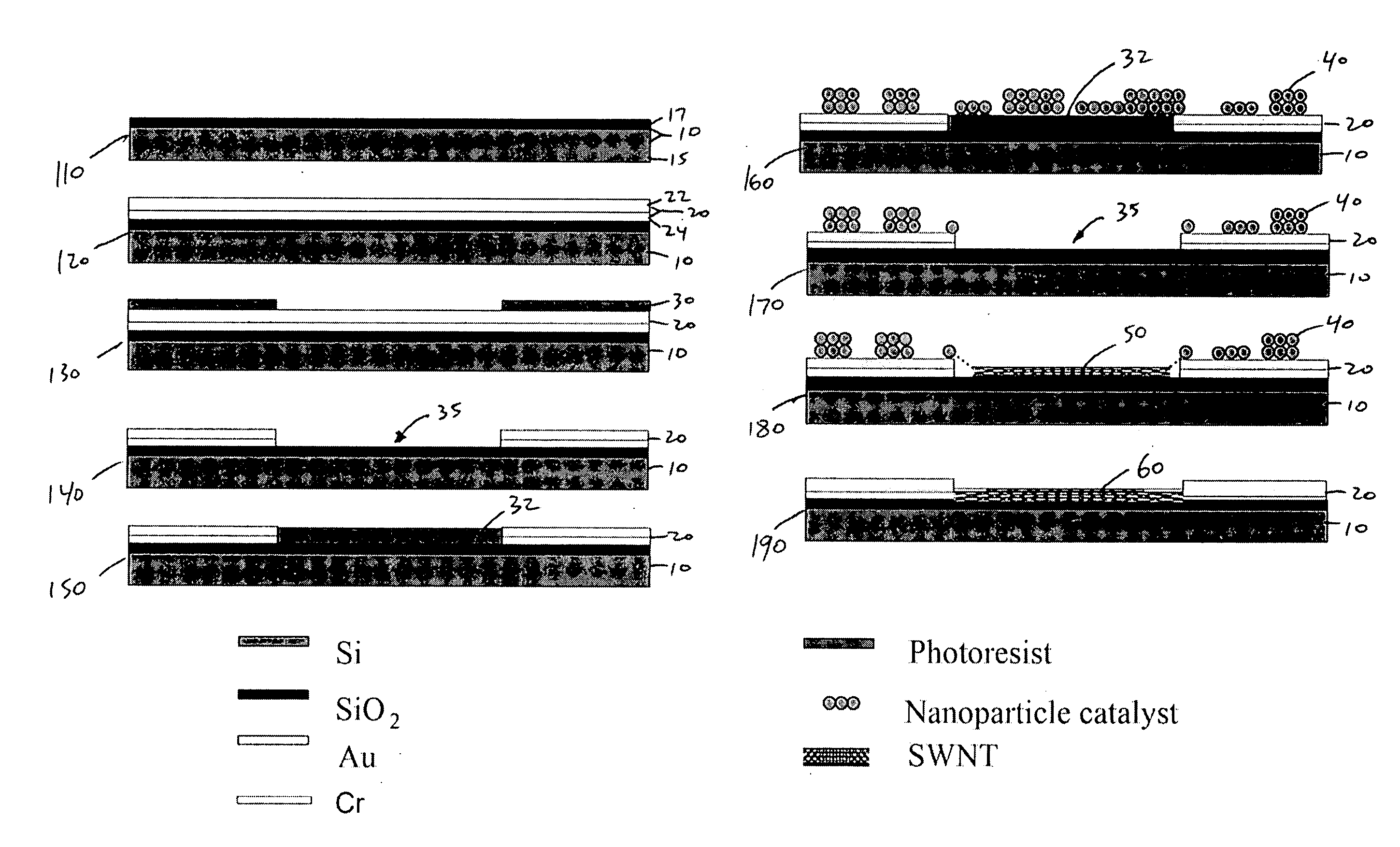
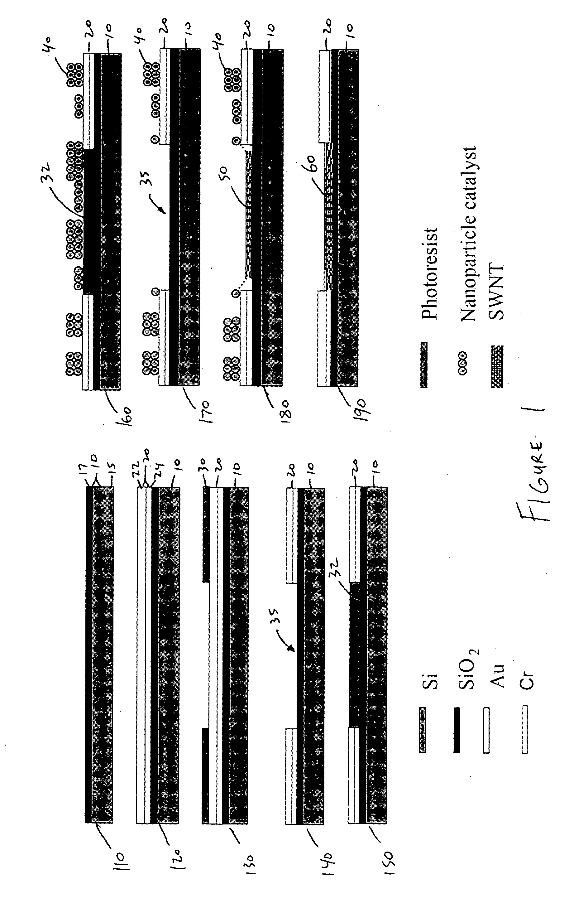
[0027]FIG. 1 depicts an exemplary method of synthesizing single-walled carbon nanotubes. The methods disclosed herein can also be modified to form multi-walled carbon nanotubes. In step 110, a substrate 10 is prepared according to cleanroom standards. The substrate 10 can comprise a lower, primary layer 15 and an upper, insulating layer 17. The primary layer 15 of the substrate 10 preferably includes silicon (Si). The insulating layer 17 can comprise a material such as silicon dioxide (SiO2), silicon nitride (Si3N4), or the like. In one exemplary embodiment, the substrate is a four inch silicon wafer with a 500 nm thick silicon dioxide (SiO2) film. The silicon wafer can be of any form known in the art. In one exemplary embodiment, the silicon wafer is a 100, p-type with a resistivity of about 12-16 kΩ-cm. The substrate 10 can also be comprised of other suitable materials such as a glass, a ceramic, a sapphire, a metal, a semiconductor material, or other materials known in the art.

[002


PUM

PropertyMeasurementUnit
Lengthaaaaaaaaaa
Flow rateaaaaaaaaaa
Diameteraaaaaaaaaa

Abstract

Systems and methods for synthesizing long carbon nanotubes and using the nanotube as an electrical conductor. A substrate is provided with one or more metal underlayer platforms that allow the nanotube to grow freely suspended from the substrate. A modified gas-flow injector is used to reduce the gas flow turbulence during nanotube growth. Nanotube electrodes are formed by growing arrays of aligned nanotubes between two metal underlayer platforms.

Description


Claims


Application Information

Patent Timeline
Owner RGT UNIV OF CALIFORNIA
Why Eureka
Try Eureka