Ultrasound, Probe, Ultraonograph, And Ultrasonigraphy
- Summary
- Abstract
- Description
- Claims
- Application Information
AI Technical Summary
Benefits of technology
Problems solved by technology
Method used
Image

Examples
Example
Example 1
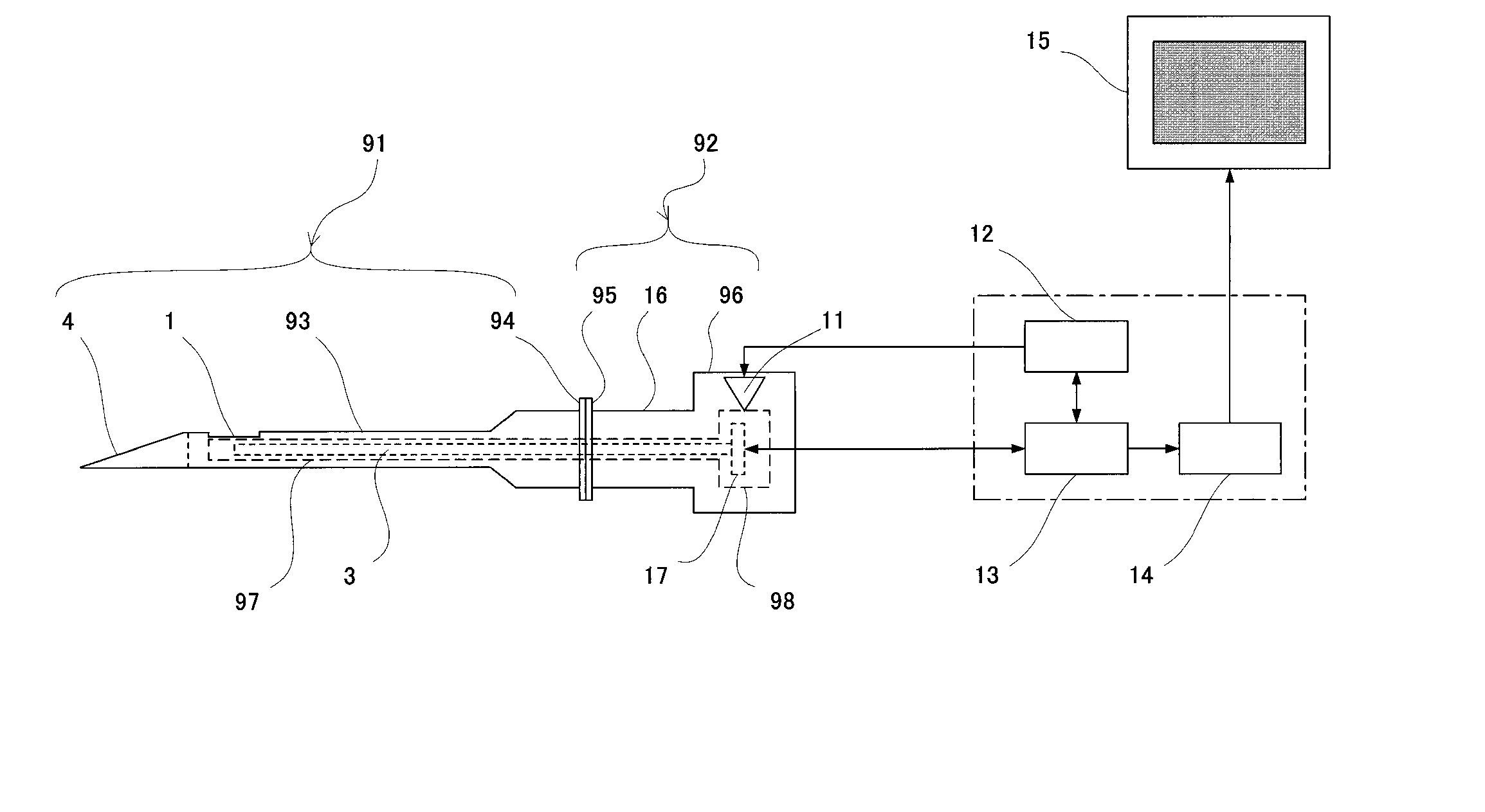
[0113]FIG. 1 shows the overall structure of the invented needle-type ultrasonograph.
[0114]FIG. 1 shows that the outer frame of the ultrasound probe is a hollow tube with a puncture needle portion (91) on one end and an extended portion (92) on its other end.
[0115] The puncture needle portion (91) is the part of the outer frame that is inserted into body tissue and is consisted of a hollow outer frame (93) with the sharpened tip (4) at the other end.
[0116] The extended portion (92) is equipped with an extended part (96) at one end; and the puncture needle portion (91) and the extended portion (92) are joined by connectors (94, 95).
[0117] The inner diameter of the extended part (96) of the extended portion (92) is larger than that of the outer frame (93) of the puncture needle portion (91).
[0118] The hollow inner tube (97) is placed inside the outer frame through the puncture needle portion (91) and the extended portion (92). The expanded part (98) of the inner tube is hou
Example
Example 2
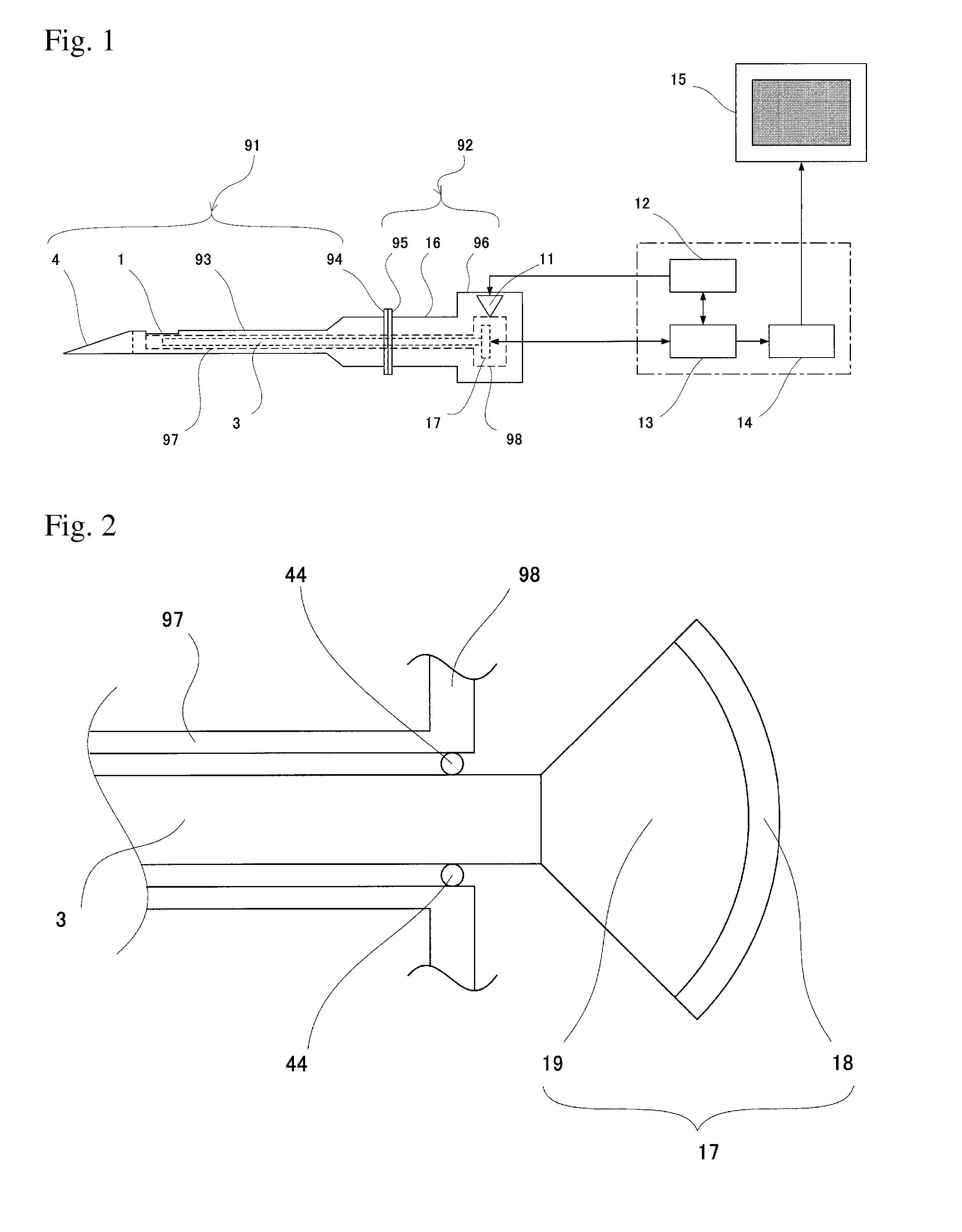
[0132]FIG. 2 is a schematic embodiment of the transducer (17). The transducer element (18) generates an ultrasonic wave.
[0133] According to the design of the invention, because the transducer is placed outside the body, an ultrasound transducer 1 to 30 mm in diameter can be used, thus providing much more power.
[0134] The transducer element (18) is attached to the fiber (3).
[0135]FIG. 2 shows that the fiber (3) can be extended to the position where the transducer (17) is connected, and the transducer element (17) and the fiber (3) are connected by the acoustic medium (19), which is made of the same material as that of the fiber (3).
[0136] Regarding the fiber (3) as shown FIG. 2, a thin sapphire or fused quartz fiber can be used as an acoustic waveguide.
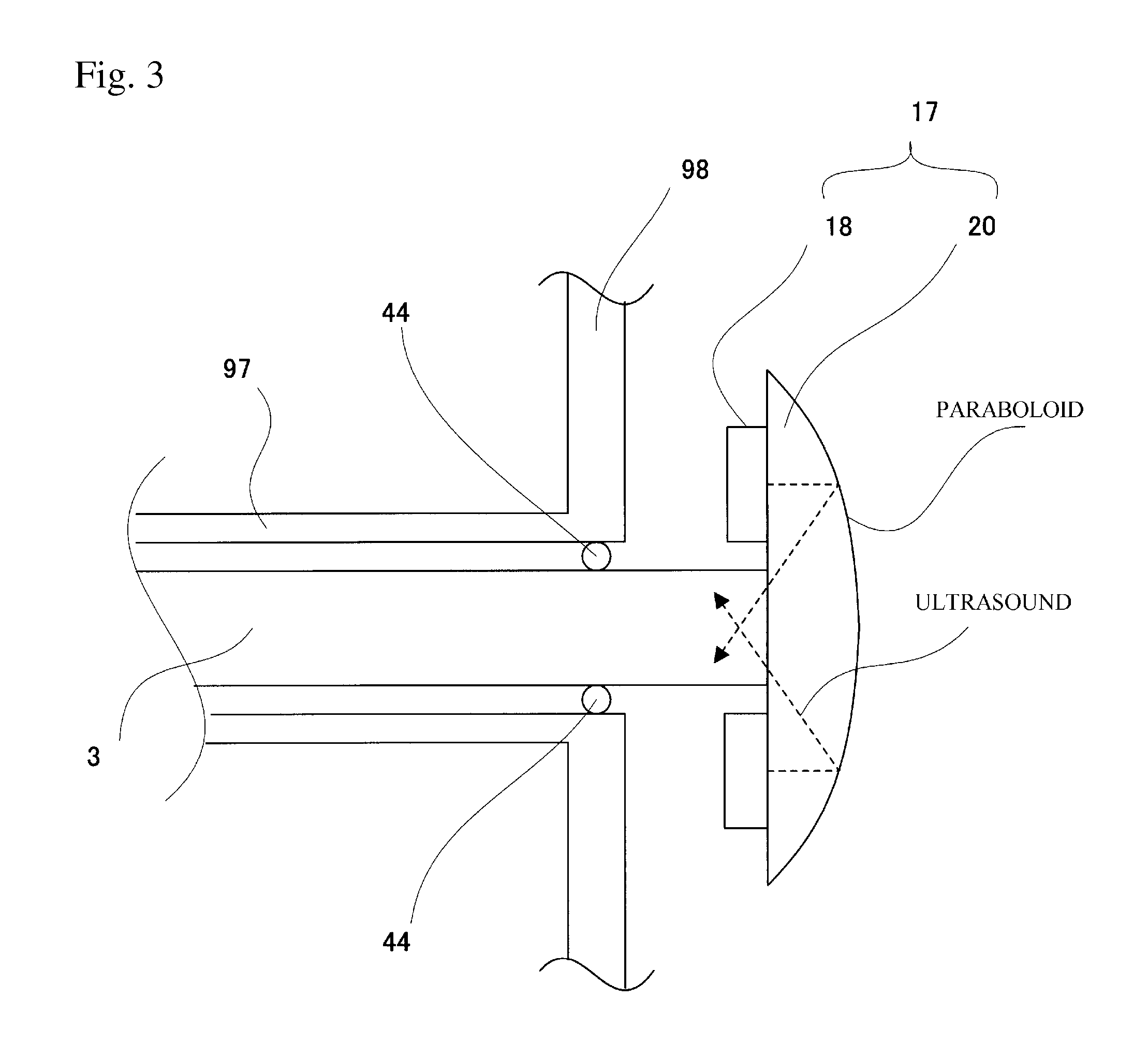
[0137] In FIG. 2, ultrasonic waves converge on the end face of the fiber (3) using a concave transducer (18), transmitting a large amount of ultrasonic energy to the fiber (3) via the acoustic medium (19)
[0138] The acousti
Example
Example 6
[0188]FIG. 9 shows the second embodiment of the invented ultrasonograph, which differs from that described in Example 1, the inner tube (97) having been removed, the fiber (3) having been placed inside the bore of the outer frame, and the ultrasound beam deflection device, mirror (2), having been attached to the tip of the bore of the outer frame (93) of the puncture needle portion (91) (not shown).
[0189] Accordingly, the beam is transmitted in a fixed direction, and scanning is not performed. Because, the inner tube has been eliminated, the outer diameter of the outer frame (93) of the puncture needle portion (91) can be smaller and the diameter of the fiber can be larger than those represented in Example 1, or the manufacturing tolerances of the diameters can be greater.
[0190] This embodiment can be used for A-mode or M-mode presentation.
PUM
 Abstract
Description
Claims
Application Information
 - R&D Engineer
- R&D Manager
- IP Professional
- Industry Leading Data Capabilities
- Powerful AI technology
- Patent DNA Extraction
Browse by: Latest US Patents, China's latest patents, Technical Efficacy Thesaurus, Application Domain, Technology Topic.
© 2024 PatSnap. All rights reserved.Legal|Privacy policy|Modern Slavery Act Transparency Statement|Sitemap