Light-emitting element using spirofluorene derivative and electronic appliance
a technology of spirofluorene and light-emitting element, which is applied in the direction of discharge tube luminescnet screen, organic chemistry, natural mineral layered products, etc., can solve the problems of difficult generation of triplet excited molecules and oxygen addition reactions, and achieve high t1 level, high luminous efficiency, and high hole-transporting property
- Summary
- Abstract
- Description
- Claims
- Application Information
AI Technical Summary
Benefits of technology
Problems solved by technology
Method used
Image

Examples
embodiment mode 1
[0080]In Embodiment Mode 1, a concept of a light-emitting element of the present invention will be explained.
[0081]In recent years, the present inventors have focused on phosphorescent compounds to achieve high performance of light-emitting elements and examined light-emitting elements using a wide variety of phosphorescent compounds. As one result thereof, the present inventors have found that by using a spiro-9,9′-bifluorene derivative to which one amino group is bonded is used, a light-emitting element containing a phosphorescent compound can provide light emission with very high efficiency compared to light-emitting elements using a phosphorescent compound which have been reported so far.
[0082]Through the property evaluation made by the present inventors, it was found that the T1 level of the spiro-9,9′-bifluorene derivative is high. That is, it was found that triplet excitation energy is difficult to transfer from other layers to a layer including the spiro-9,9′-bifluorene derivat
embodiment mode 2
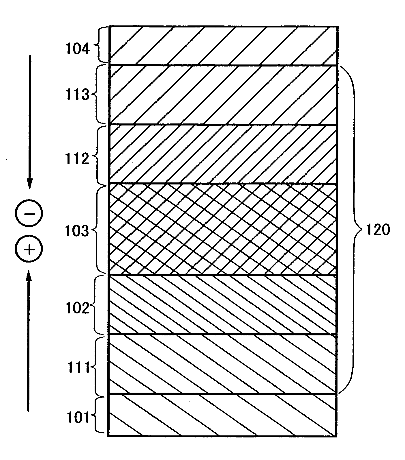
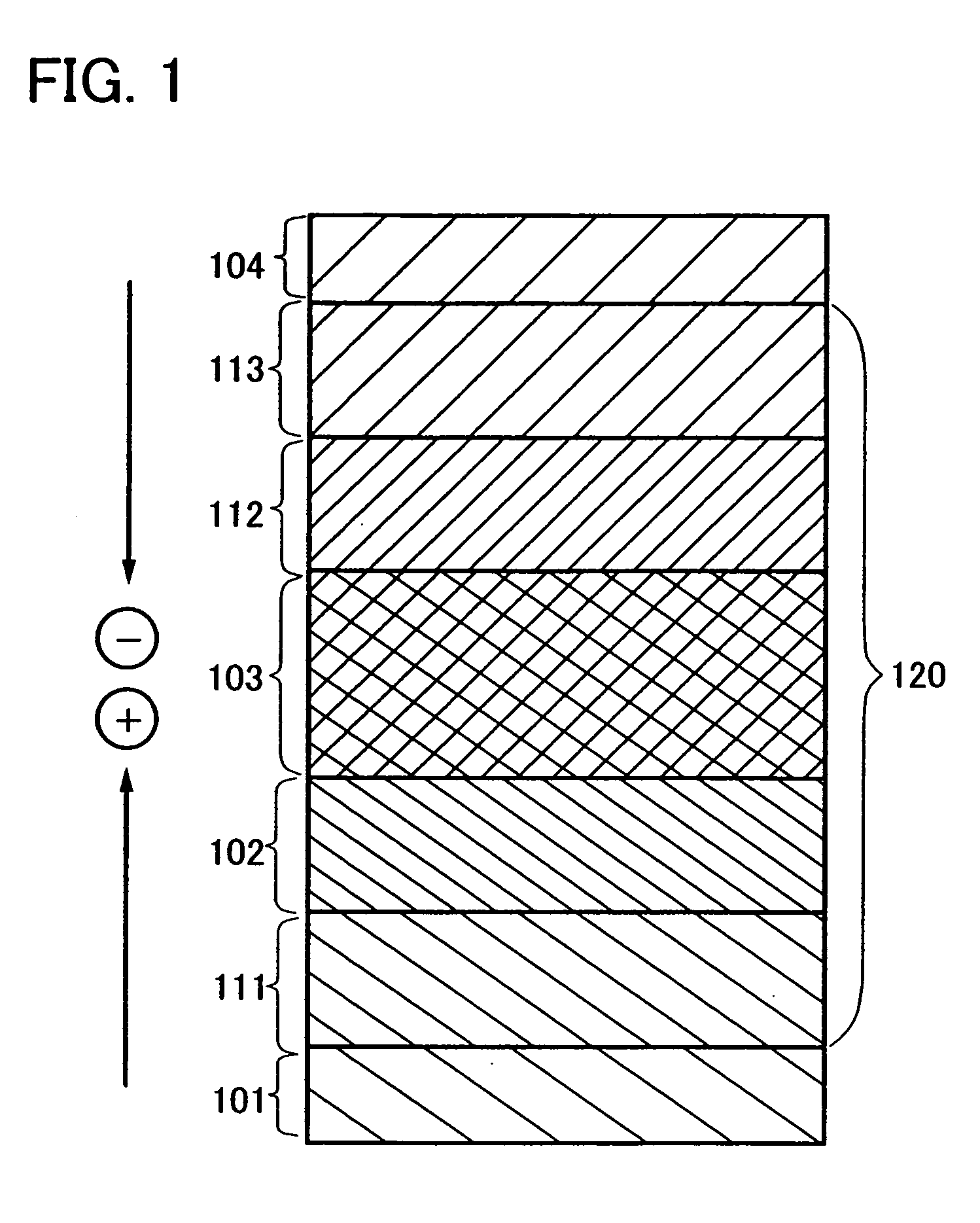
[0088]In Embodiment Mode 2, a structure of a light-emitting element of the present invention will be explained with reference to FIG. 1.
[0089]FIG. 1 is a view illustrating a light-emitting element having a layer 120 containing an organic compound between a first electrode 101 and a second electrode 104. The layer 120 containing an organic compound includes a first layer 102 containing a spiro-9,9′-bifluorene derivative and a second layer 103 containing a phosphorescent compound.
[0090]Here, the second layer 103 containing a phosphorescent compound is preferably a layer in which a substance with triplet excitation energy larger than that of the phosphorescent compound is used as a host material and the phosphorescent compound is dispersed as a guest material. Dispersing the phosphorescent compound which is a substance serving as an emission center can prevent light emitted from the phosphorescent compound from being quenched due to the concentration.
[0091]A phosphorescent compound is not
embodiment mode 3
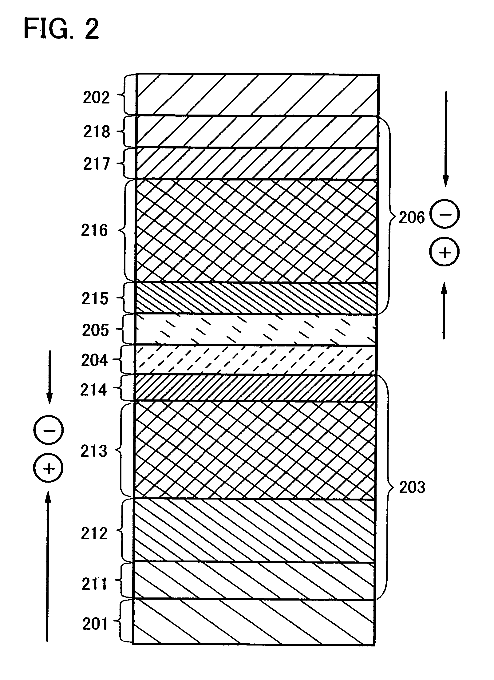
[0162]In Embodiment Mode 3, a light-emitting element with different element structure from that of Embodiment Mode 2 is exemplified in which a plurality of first layers containing a spiro-9,9′-bifluorene derivative and second layers containing a phosphorescent compound are provided and each of second layers containing phosphorescent compounds emits light. Accordingly, light that is a combination of light emitted from the plurality of light-emitting layers can be obtained. In Embodiment Mode 3, a mode of the light-emitting element including a plurality of first layers containing spiro-9,9′-bifluorene derivatives and second layers containing phosphorescent compounds will be explained with reference to FIG. 2.
[0163]A light-emitting element in FIG. 2 includes a layer A 203 containing an organic compound and a layer B 206 containing an organic compound between a first electrode 201 and a second electrode 202. The layer A 203 containing an organic compound includes a first layer 212 containi
PUM
| Property | Measurement | Unit |
|---|---|---|
| Light | aaaaa | aaaaa |
| Luminous efficiency | aaaaa | aaaaa |
| Phosphorescence quantum yield | aaaaa | aaaaa |
Abstract
Description
Claims
Application Information
 - R&D Engineer
- R&D Manager
- IP Professional
- Industry Leading Data Capabilities
- Powerful AI technology
- Patent DNA Extraction
Browse by: Latest US Patents, China's latest patents, Technical Efficacy Thesaurus, Application Domain, Technology Topic.
© 2024 PatSnap. All rights reserved.Legal|Privacy policy|Modern Slavery Act Transparency Statement|Sitemap