Charging device, image forming apparatus, control method of charging device, control program, computer-readable storage medium recording control program

Inactive Publication Date: 2009-01-01
SHARP KK
View PDF9 Cites 1 Cited by
  • Summary
  • Abstract
  • Description
  • Claims
  • Application Information

AI Technical Summary

Benefits of technology

[0020]Here, in order to prevent deterioration (life deterioration) due to operation of the device, it is preferable that the amount of ions is increased by increasing the frequency under a condition where discharge is performed stably and, then, after the frequency reaches an upper limit of a setting of the frequency, the amount of ions generated is corrected by increasing the applied voltage. This is because an unnecessary increase of the applied voltage could reduce the life duration of the devi

Problems solved by technology

However, element deterioration easily progresses when the applied voltage is increased

Method used


Image

  • Charging device, image forming apparatus, control method of charging device, control program, computer-readable storage medium recording control program
  • Charging device, image forming apparatus, control method of charging device, control program, computer-readable storage medium recording control program
  • Charging device, image forming apparatus, control method of charging device, control program, computer-readable storage medium recording control program

Examples


Embodiment Construction

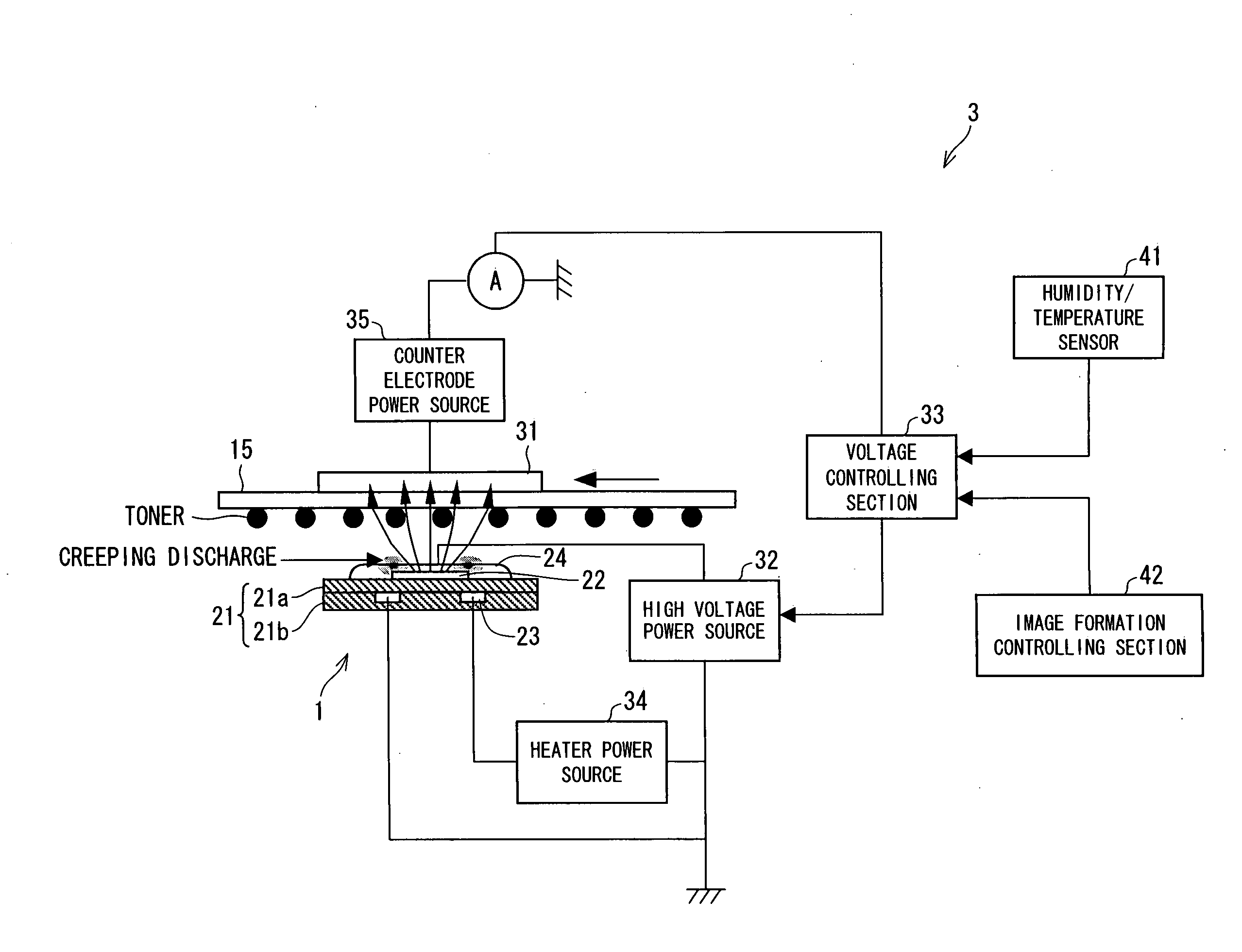
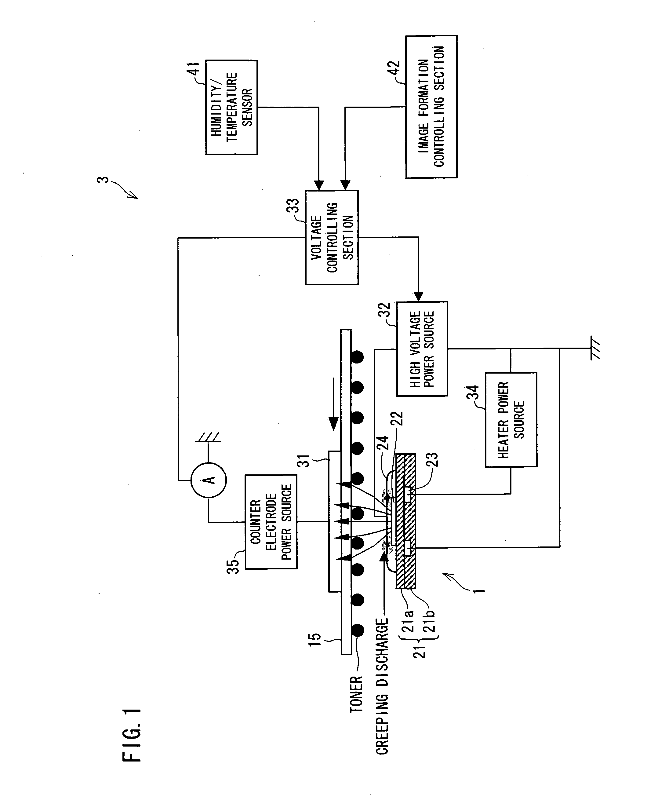
[0032]The following specifically explains one embodiment of a charging device of the present invention and an image forming apparatus that includes the charging device, with reference to FIGS. 1 through 9. Note that the following embodiment is one example exemplifying the present invention, and by no means limits a technical scope of the present invention.

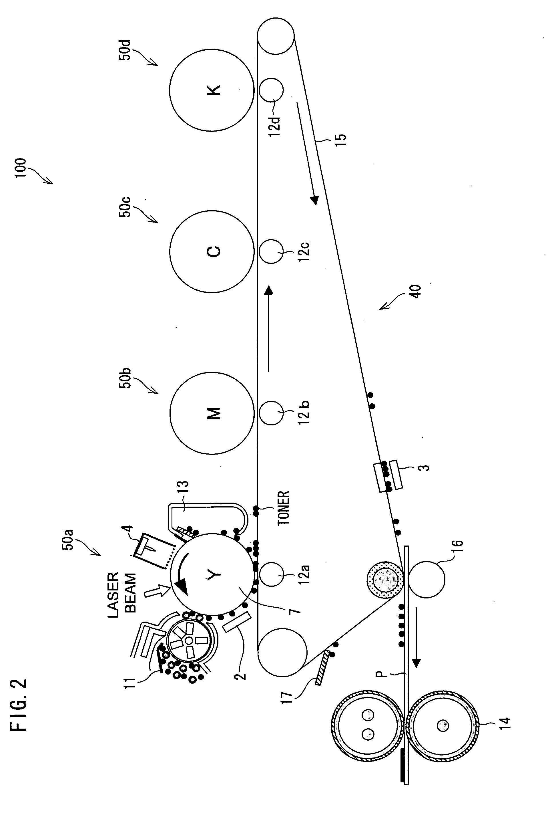
[0033]First, the following explains a whole arrangement of the image forming apparatus according to the present embodiment. FIG. 2 is a cross sectional view schematically illustrating an arrangement of an image forming apparatus 100 according to the present embodiment. This image forming apparatus 100 is a tandem type printer employing an intermediate transfer system, and can form a full color image.

[0034]As illustrated in FIG. 2, the image forming apparatus 100 includes visible image forming units 50a to 50d for four colors (C, M, Y, and K), a transfer unit 40, and a fixing device 14.

[0035]The transfer unit 40 includes an intermediat


PUM


Abstract

In a charging device of the present invention, with reference to a state (movement speed of a charging receiving material, operating period of charging device) in which the charging device is used which state is obtained by an image formation controlling section, a voltage controlling section sets or changes an applied voltage to be applied between a discharge electrode and an inductive electrode. Accordingly, even in a case where discharge is hard to occur, a necessary amount of ions can be supplied stably.

Description


Claims


Application Information

Patent Timeline
Owner SHARP KK
Why Eureka
Try Eureka