Optical fiber sensor
- Summary
- Abstract
- Description
- Claims
- Application Information
AI Technical Summary
Benefits of technology
Problems solved by technology
Method used
Image

Examples
embodiment 1
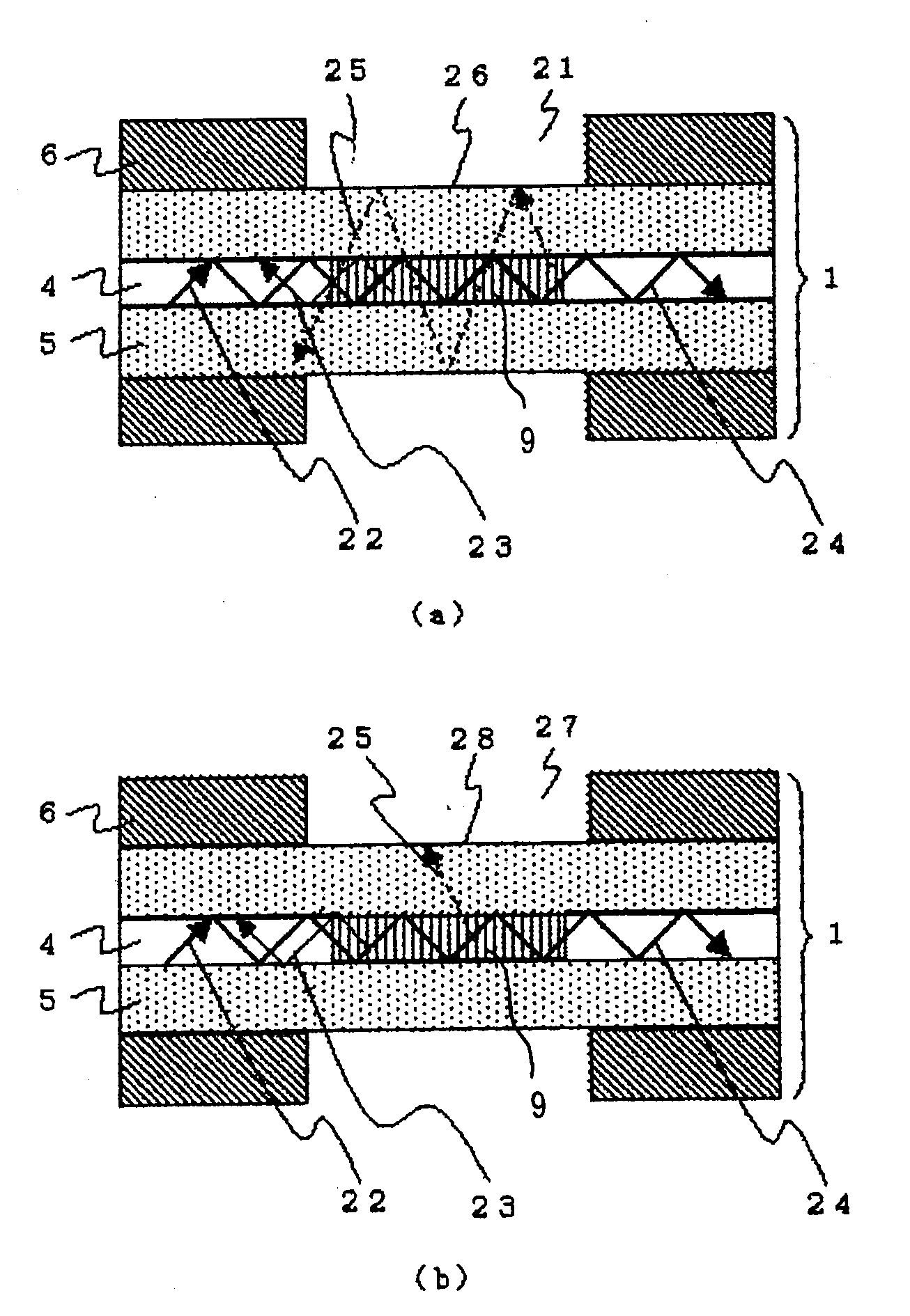
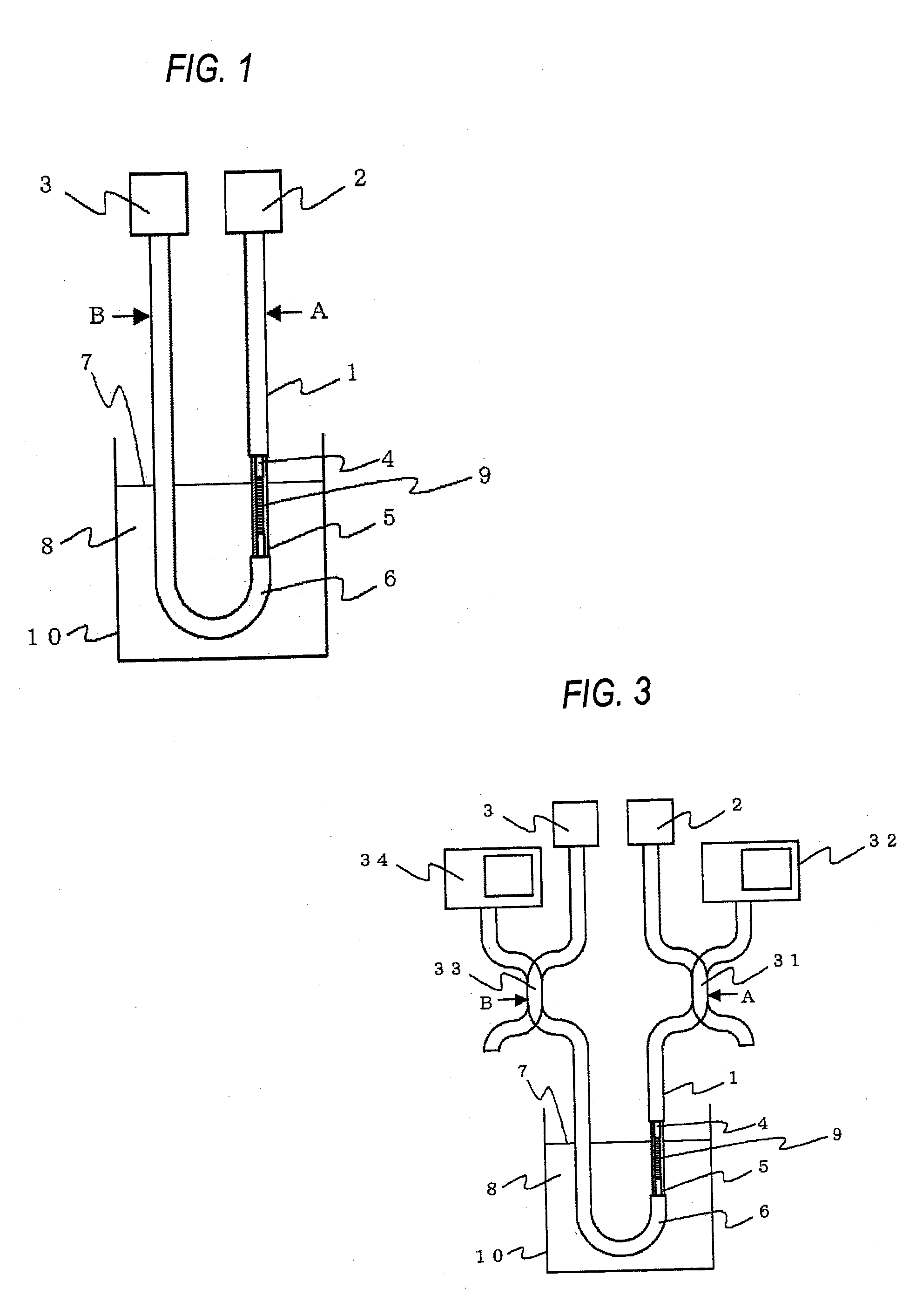
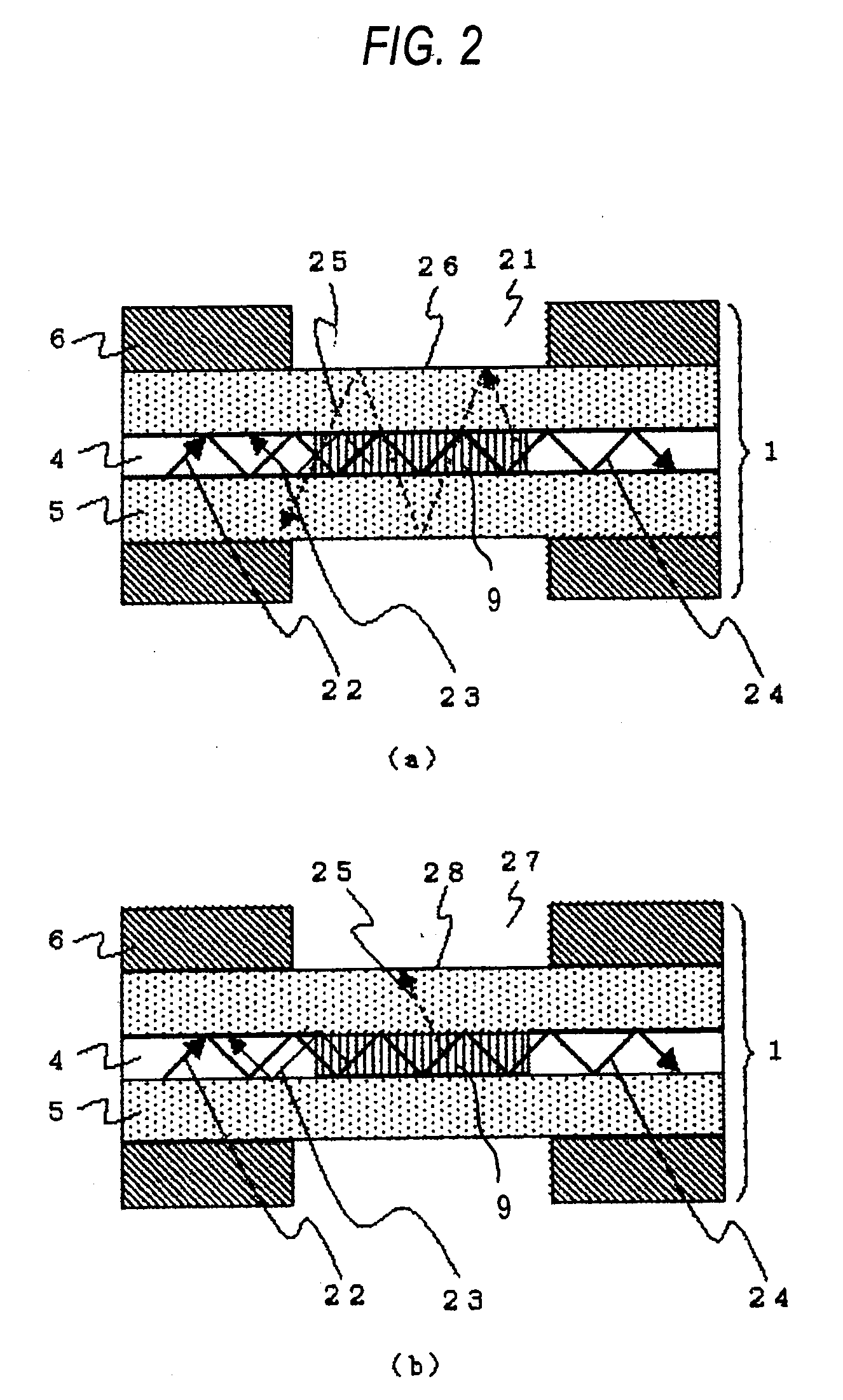
[0060]FIG. 1 is a schematic diagram showing an optical fiber sensor for detecting the liquid level according to an embodiment 1 implementing the present invention. In FIG. 1, a light source 2 is disposed at one end portion of the optical fiber 1, and a light receiving unit 3 is disposed at the other end portion. The optical fiber 1 is equipped with a core 4 through which light emitted from the light source 2 propagates, a clad 5 covering the core 4 so that light is confined in the core 4, and a fiber jacket 6 which covers and protects the above elements. A part of the fiber jacket 6 is removed so that the clad 5 is brought into direct contact with liquid 8 to measure the height of the liquid level 7. The portion from which a part of the fiber jacket 6 is removed is disposed substantially in parallel to the variation direction of the liquid level 7, and a grating 9 is formed at the core 4 corresponding to this portion. The optical fiber 1 is bent in an U-shape in the neighborhood of the
embodiment 2
[0073]In the embodiment 1, light reaching the light receiving unit also contains light of a large-loss wavelength area which is not relevant to occurrence of the cladding mode and appears at the center of the transmission spectrum. For example, when a photodiode for measuring the intensity of light is used as the light receiving unit, a part of the light intensity to be measured is the light intensity irrelevant to the occurrence of the cladding mode, and thus the variation amount of the light intensity is relatively small due to the loss caused by the cladding mode, so that it would be impossible to enhance the measurement sensitivity. In the embodiment 2, the light of the wavelength area irrelevant to the occurrence of the cladding mode is excluded from the measurement.
[0074]FIG. 7 is a schematic diagram showing a liquid level detecting sensor according to this embodiment. In this embodiment, in the same construction as the embodiment 1, an optical filter 71 is disposed at the portio
embodiment 3
[0076]In the embodiment 2, the light reflected from the optical filter may return to the light source or the grating to induce unnecessary interference, so that it becomes a noise component. In the embodiment 3, the light reflected from the optical filter is prevented from returning to the light source or the grating.
[0077]FIG. 9 is a schematic diagram showing a liquid level detecting optical fiber sensor according to this embodiment. In this embodiment, in the same construction as the embodiment 2, a circulator 91 is disposed between the liquid level 7 and the optical filter 71, and the light reflected from the optical filter 71 is guided to a terminating unit 92 by the circulator 91. The circulator 91 has three ports 91a, 91b and 91c. The terminating unit 92 is a fiber coil of 10 mm or less in diameter. A photodiode for measuring the light intensity is used as the light receiving unit 3, for example.
[0078]The operation of this embodiment will be described. Light emitted from the ligh
PUM
 Abstract
Description
Claims
Application Information
 - R&D Engineer
- R&D Manager
- IP Professional
- Industry Leading Data Capabilities
- Powerful AI technology
- Patent DNA Extraction
Browse by: Latest US Patents, China's latest patents, Technical Efficacy Thesaurus, Application Domain, Technology Topic.
© 2024 PatSnap. All rights reserved.Legal|Privacy policy|Modern Slavery Act Transparency Statement|Sitemap