Single Output H-Bridge Drive

a single output, drive technology, applied in the direction of motor/generator/converter stopper, dynamo-electric converter control, instruments, etc., can solve the problem of rotating the rotor

Active Publication Date: 2009-06-18
MINEBEAMITSUMI INC
View PDF3 Cites 9 Cited by
  • Summary
  • Abstract
  • Description
  • Claims
  • Application Information

AI Technical Summary

Benefits of technology

This patented technology allows for better efficiency when utilizing a computer's memory system (RAM). It uses different signals from both switches and controls to determine how fast it operates on its own without causing any problems like flashing lights caused by too much power consumption. Additionally, this design helps avoid issues such as shunting currents during certain times while still allowing enough energy to work properly. Overall, this innovation improves performance and reliability of RAM systems.

Problems solved by technology

This patented describes how electrical power from one type of source works with another's magnetic field without causing any damage or malfunctions. However, it also explains why this work cannot happen smoothly due to variations caused by factors like temperature fluctuations over time. To solve these issues, there has been developed various methods and devices called "driving circuits," which help maintain consistently high performance levels despite varying environmental conditions.

Method used


Image

  • Single Output H-Bridge Drive
  • Single Output H-Bridge Drive
  • Single Output H-Bridge Drive

Examples


Embodiment Construction

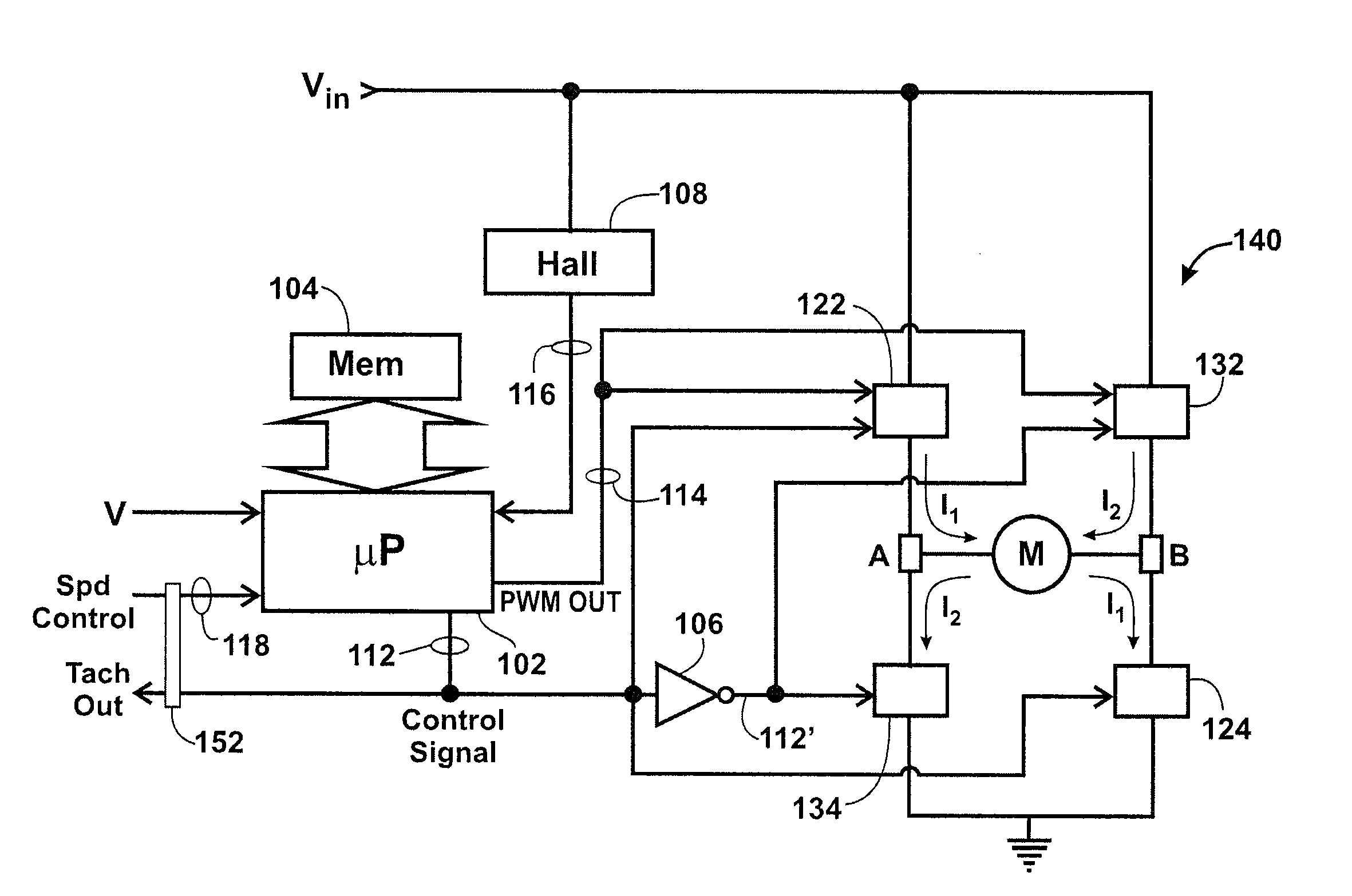
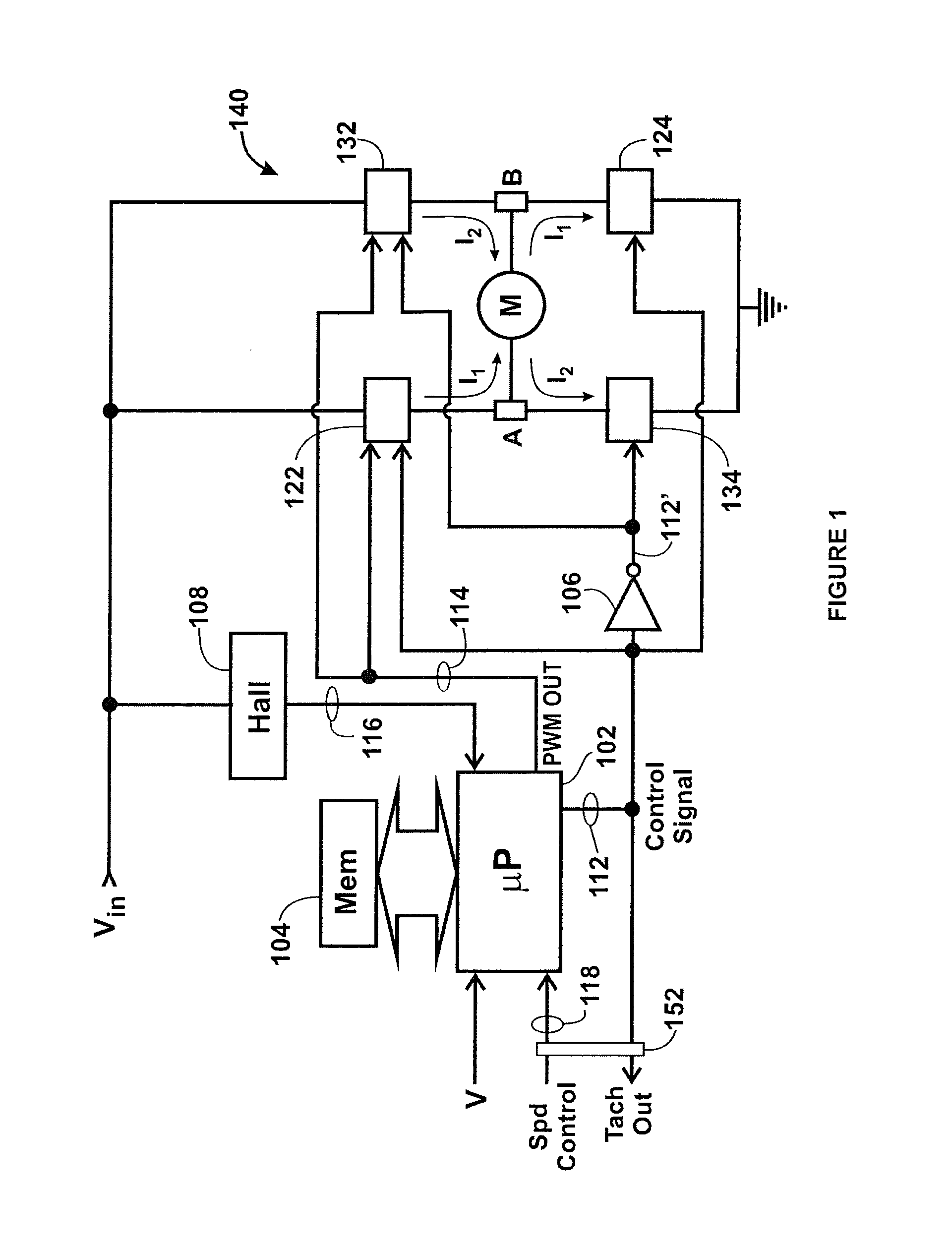
[0011]FIG. 1 illustrates a generalized block diagram of components of a drive circuit according to the present invention for producing and delivering the drive current to the winding of a bipolar brushless DC motor M.

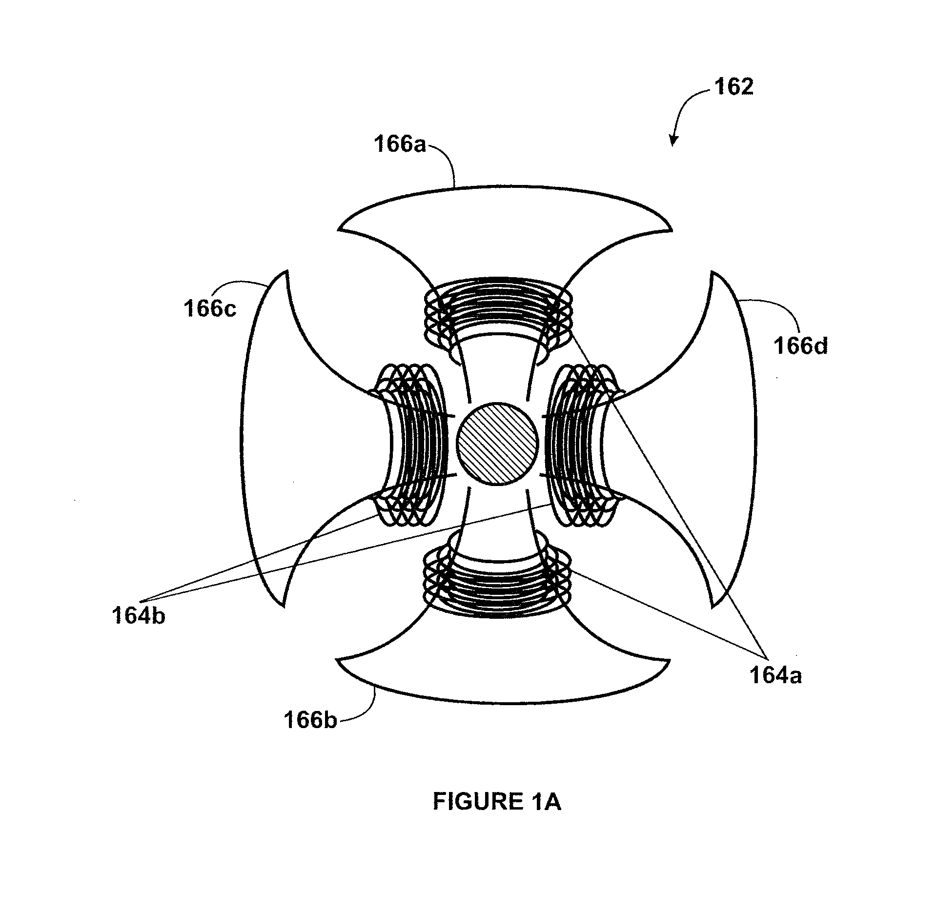
[0012]FIG. 1A shows the stator winding 162 (4 tooth, 4 slot) for a bipolar motor. The particular bipolar configuration shown in the figure uses a four slot stator 162 with stator windings on each of the four teeth 166a-166d. It will be appreciated that the present invention can be used with other slot configurations.

[0013]In the stator winding 162 shown in FIG. 1A, commutation involves driving current through pairs of the stator windings in synchrony with the rotor. There is a single winding that wraps around all four stator teeth 166a-166d, but they are wound in alternating clockwise and counter-clockwise orientations. Thus, in a bipolar motor, the windings 164a, 164b shown in FIG. 1A represent two segments of a single winding. Thus, if segment 164a is wound around both t


PUM


Abstract

Disclosed is a drive circuit for generating the drive current used to energize the windings of a motor. The drive circuit includes a data processing unit that produces two outputs used to control an H-bridge and generation of the drive current. One output, a commutation signal, controls the timing of generation of drive current. The drive current in turn is determined based on the other output, a speed signal. The speed signal waveform includes blanking portions to avoid occurrences of shoot through in the H-bridge.

Description


Claims


Application Information

Patent Timeline
Owner MINEBEAMITSUMI INC
Why Eureka
Try Eureka