Sheet feeder

Active Publication Date: 2009-10-01
RAUTE OY
View PDF15 Cites 7 Cited by
  • Summary
  • Abstract
  • Description
  • Claims
  • Application Information

AI Technical Summary

Benefits of technology

[0008]The basic structure of the apparatus according to the invention is formed by an apparatus comprising, as known in the art, separate lifting elements gripping by suction to the upper surface of the sheet-like object to be transferred, the lifting elements being positioned in one or several rows extending in one direction over the stack of the sheet-like objects, and transfer elements for transferring the lifted sheet-like objects. According to the characteristics of one embodiment of the invention, the apparatus comprises means to observe the topmost surface of the stack of the

Problems solved by technology

The devices operate without problems with full-sized veneer sheets, but problems are caused by random veneer layers consisting of narrower sheets than the sheets with full width.
In spite of careful compiling of the layers in the stack, whether made manually or by machine, there are mistakes occurring when compiling the layers, as a result of which there can be sheets in a layer more or less overlapping each other.
A part of the sheets taken along with the suction gripping de

Method used


Image

  • Sheet feeder
  • Sheet feeder
  • Sheet feeder

Examples


Embodiment Construction

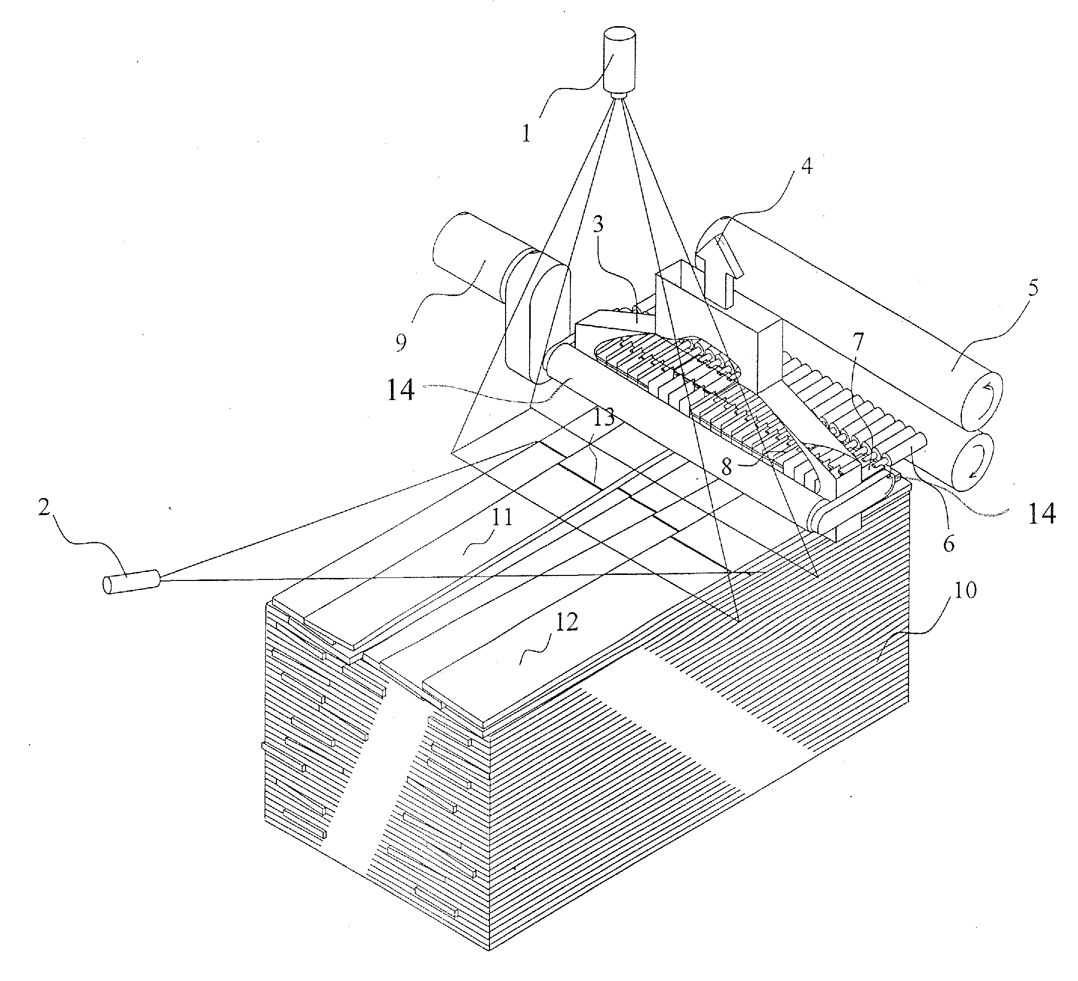
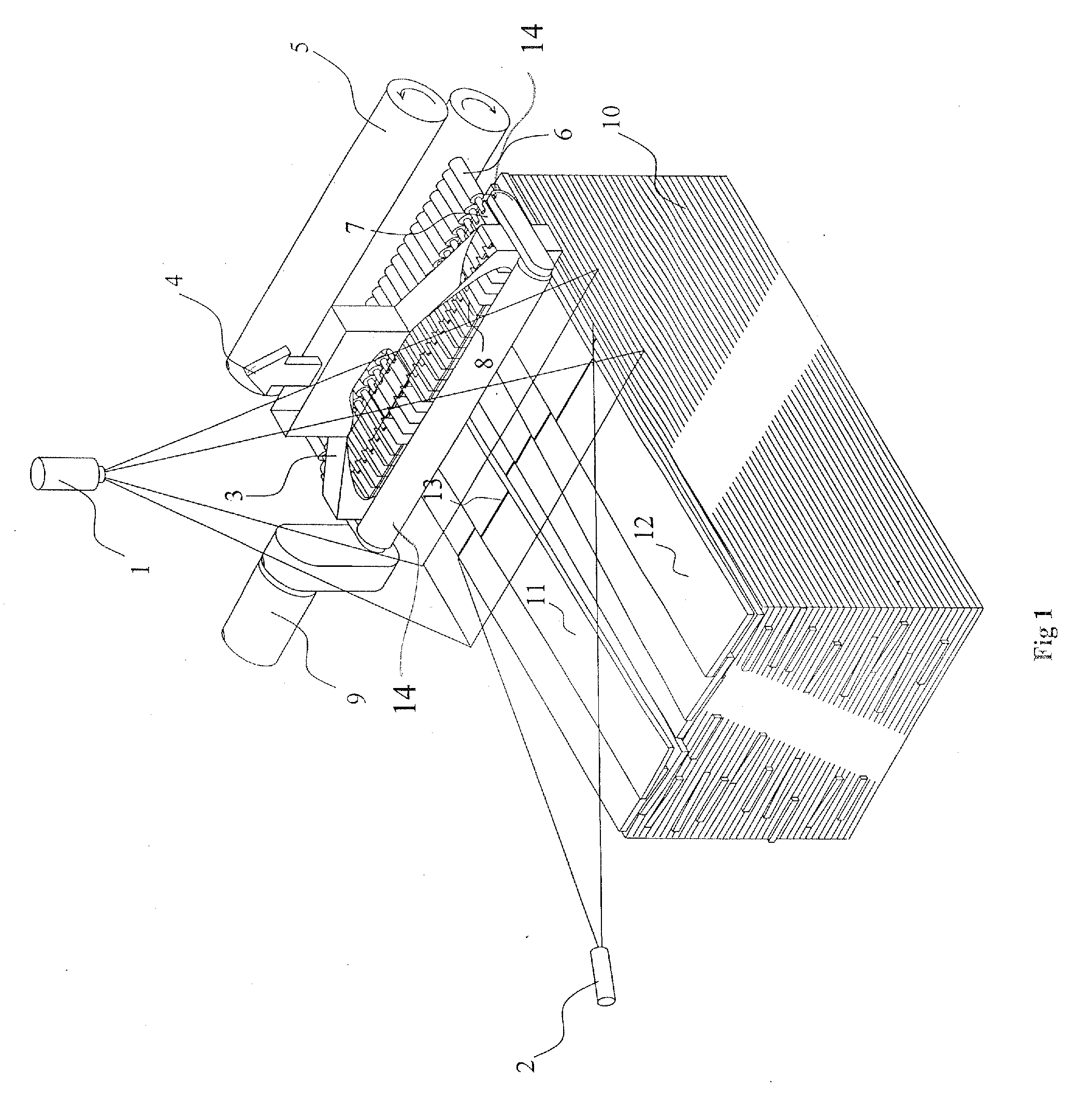
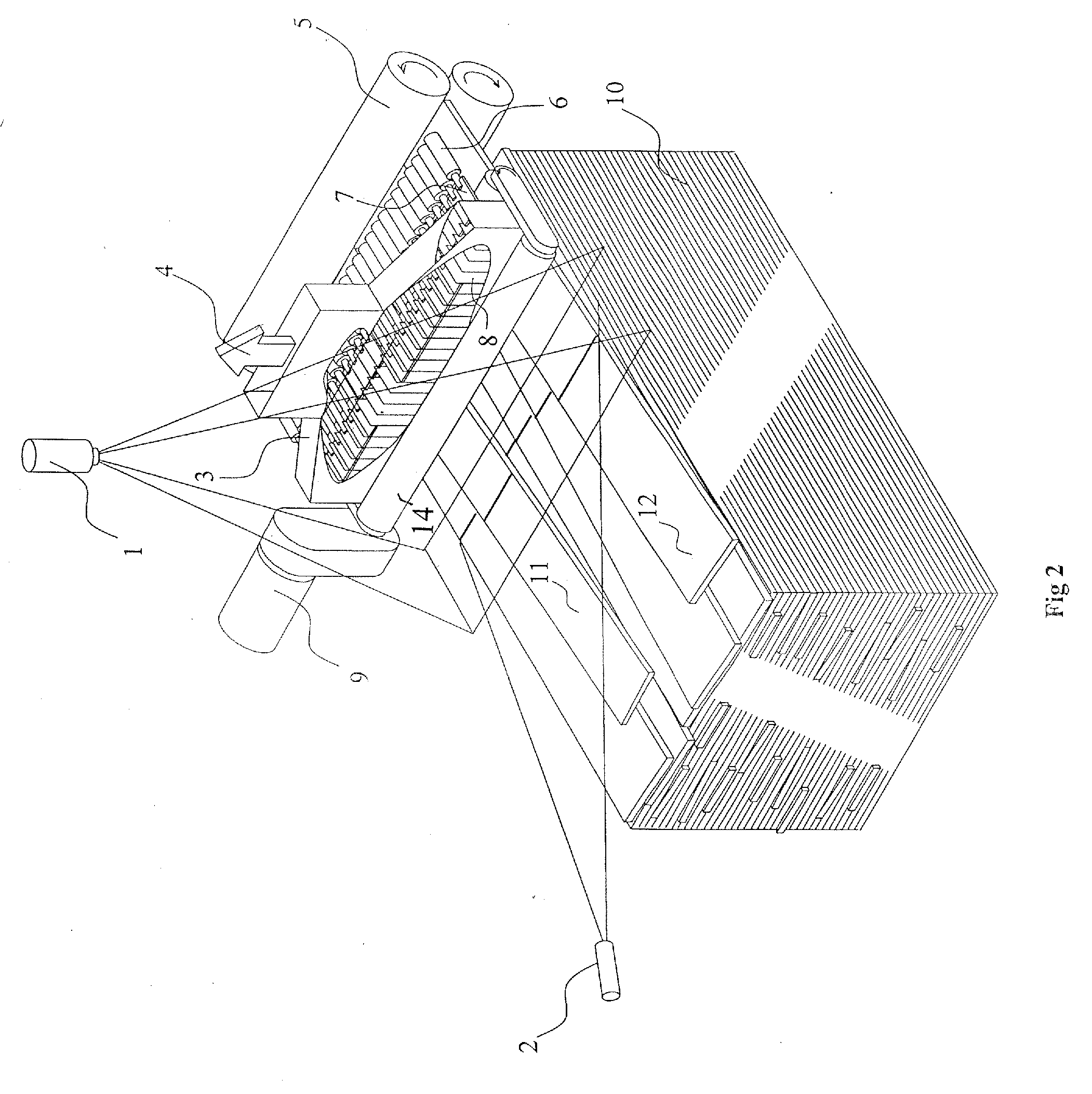
[0014]FIG. 1 shows schematically a veneer stack 10, where veneer sheets are being removed from, layer by layer, to be forwarded to further processing, like drier. The veneer layer is lifted from the stack by means of suction lifting devices 8 operative in the vicinity of the upper surface of the veneers. When the suction effect 4 is active, the suction lifting devices grip the veneer or veneers of the uppermost veneer layer and bring them into contact with the rolls 14, keeping the lifted veneer or veneers in contact with the rolls. The rolls have rotational motion in the transfer direction, and they take the veneer or veneers in the intended transfer direction, for example to be transferred by the rolls 5. FIG. 1 shows a typical problem situation that can occur in the stack 10 in cases, where there is a layer composed of random width veneer sheets. The veneer sheets are partly overlapping. Thus, an apparatus having the construction of prior art would probably face an operating disturb


PUM


Abstract

The invention concerns an apparatus for transferring sheet-like objects from a stack, said apparatus including separate lifting elements gripping by suction to the upper surface of the sheet-like object to be transferred, positioned in a row extending over the stack of the sheet-like objects, and transfer elements for transferring the lifted sheet-like object. The suction effect of the lifting elements is controlled by means of a control device including a light source making a substantially line-shaped illumination pattern. The illumination of the light source is focused at an inclined angle to the surface of the sheet stack, substantially parallel to the lifting element row. A camera means for observing the illumination pattern forwards information about the uniformity of the uppermost layer of the stack.

Description


Claims


Application Information

Patent Timeline
Owner RAUTE OY
Why Eureka
Try Eureka