Magnetic recording medium and magnetic recording and reproducing device using the magnetic recording medium
- Summary
- Abstract
- Description
- Claims
- Application Information
AI Technical Summary
Benefits of technology
Problems solved by technology
Method used
Image

Examples
Example
Example 1
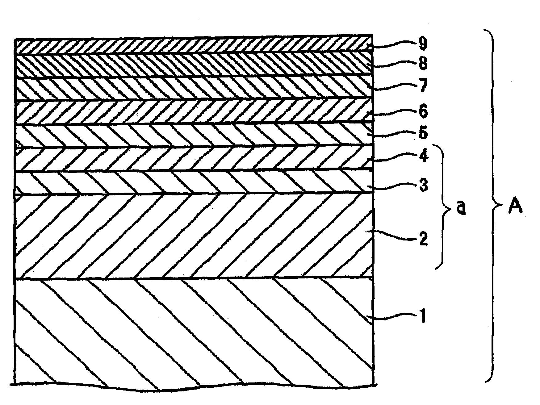
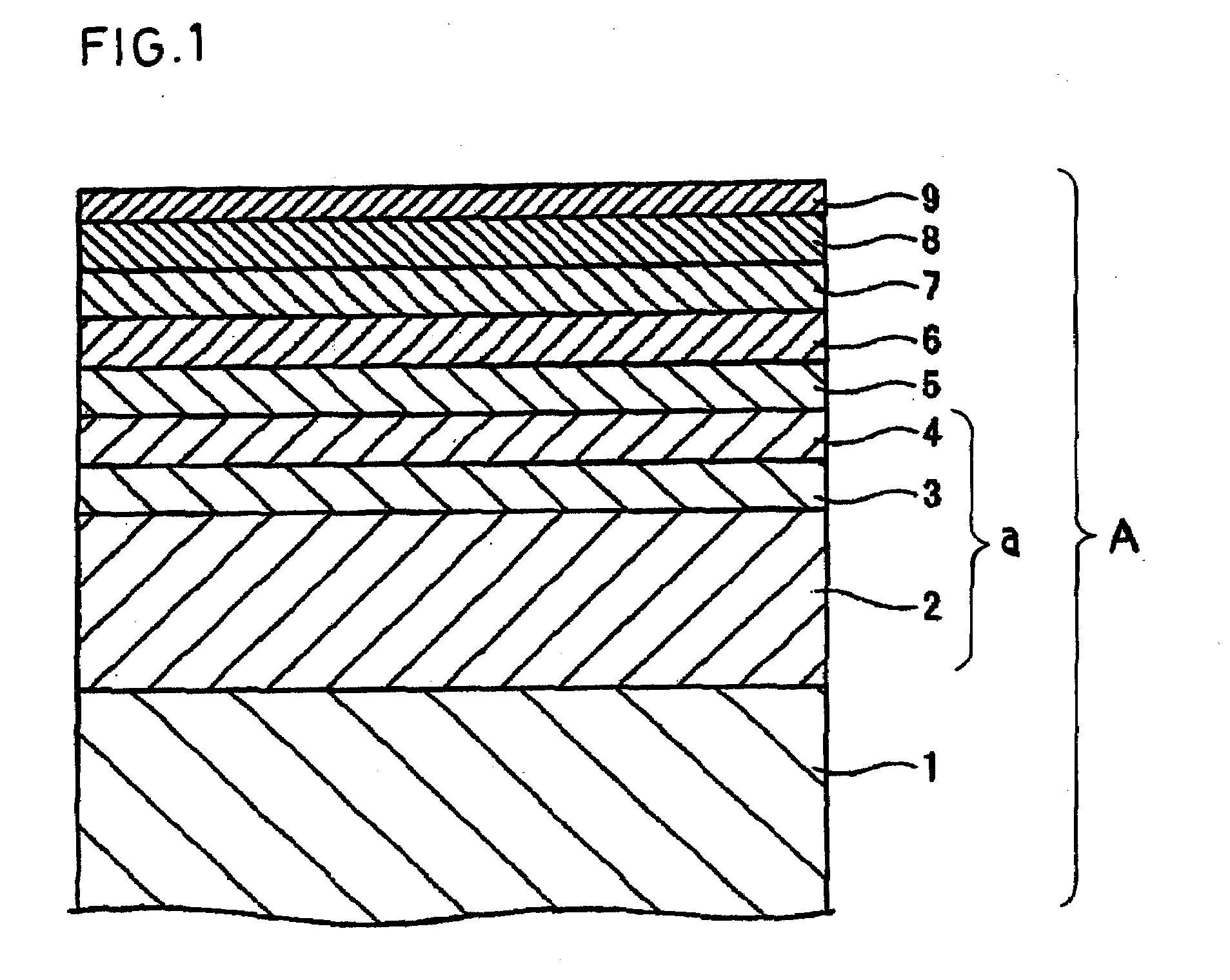
[0062]A glass substrate (an amorphous substrate 2.5 inches in diameter, made by MYG Corp. and sold under trademark designation of “MEL3”) was used as the non-magnetic substrate 1 and placed in a film-forming chamber of a DC magnetron sputtering device (made by Anelva Corp. and sold under product code of “C-3010”). The interior of the film-forming chamber was evacuated till the degree of vacuum reached 1×10⁻⁵ Pa. On this substrate, the soft under layer a was formed by stacking a film of 71Co-20Fe-5Zr-4Nb (71 atom % of Co, 20 atom % of Fe, 5 atom % of Zr and 4 atom % of Nb) in a thickness of 30 nm as the soft magnetic film 2, a Ru film in a thickness of 0.8 nm as the intervening film 3 and a film of 71Co-20Fe-5Zr-4Nb in a thickness of 30 nm as the soft magnetic film 4. The soft magnetic films 2 and 4 were confirmed by XRD to possess an amorphous structure as a crystal structure.
[0063]Subsequently, a film of 80Ni-10W was stacked in a thickness of 5 nm as the under film 5, a film
Example
Comparative Examples 1 to 3
[0066]Magnetic recording media were obtained by following the procedure of Example 1 while using Ni-20Fe, Ti and Ta instead as materials for the under film.
[0067]The magnetic recording media of Example 1 and Comparative Examples 1 to 3 were evaluated regarding a magnetostatic property and recording and reproducing property. For the evaluation of the magnetostatic property, the Kerr effect measurement system made by NEOARK Corp. was used. For the evaluation of the recording and reproducing property, the read-write analyzer (product code “RWA-1632”) and the spin stand (product code “S1701MP”) both made by Guzik Technical Enterprises of U.S.A. were used.
[0068]The recording and reproducing properties was evaluated by using a magnetic head adapted to effect writing with a monopole magnetic pole and provided in the reproducing part with a GMR element, with the recording frequency set at a linear recording density of 1000 kFCI. The overwrite (OW) property was evalua
Example
[0069]From Table 1 below it was confirmed that Example 1 surpassed Comparative Examples 1 to 3 in SNR and found that the recording and reproducing property excelled even when Ru had a small thickness, such as 12 nm.
TABLE 1Soft magnetic filmUnder filmCompositionThick-CompositionThick-Ms(atom %)ness (nm)(atom %)ness (nm)(emu / cm3)Ex. 171Co—20Fe—5Zr—4Nb30 + 3090Ni—10W5120Comp. Ex. 171Co—20Fe—5Zr—4Nb30 + 3080Ni—20Fe5780Comp. Ex. 271Co—20Fe—5Zr—4Nb30 + 30Ti50Comp. Ex. 371Co—20Fe—5Zr—4Nb30 + 30Ta50MagneticMagneto-RecordingrecordingstaticandIntermediate layerfilm (Ave.propertyreproducingCompositionThick-Δθ50crystal(Coerciveproperty(atom %)ness (nm)(deg)size: nm)force: Oe)(SNR: dB)Ex. 1100Ru123.76.4466023.2Comp. Ex. 1100Ru123.57.2438022.1Comp. Ex. 2100Ru127.27.5419019.9Comp. Ex. 3100Ru126.66.9385018.2
PUM
 Abstract
Description
Claims
Application Information
 - R&D Engineer
- R&D Manager
- IP Professional
- Industry Leading Data Capabilities
- Powerful AI technology
- Patent DNA Extraction
Browse by: Latest US Patents, China's latest patents, Technical Efficacy Thesaurus, Application Domain, Technology Topic.
© 2024 PatSnap. All rights reserved.Legal|Privacy policy|Modern Slavery Act Transparency Statement|Sitemap