Fabrication Process to Connect Branch Air Ducts to Main Air Ducts and the Fabricated Ventilating Ducts

Inactive Publication Date: 2010-08-12
ZHI LIANG
View PDF7 Cites 4 Cited by
  • Summary
  • Abstract
  • Description
  • Claims
  • Application Information

AI Technical Summary

Benefits of technology

[0023]The beneficial effects of the invention are: 1. Branch ducts and main ducts can be produced according to the invention and the position of the branch duct relative to the main duct can be adjusted according to the actual needs of installation and construction requirements, which makes the position of the branch coduct complied with the pre-installation position; 2. The main air ducts and branch air ducts can be assembled and connected at the construction site, which saves the space and expense of the storage and transportation; 3. The connection flange in the existing technology is not needed anymore. The connector and the birdsmouth which are made of the air duct itself are used to connect the main air duct and the branch air duct; 4. Having optimized the process and reduced the production hours and material consumption according to material characteristics.

Problems solved by technology

This production method is complex and inefficient.
Moreover, because the connecting flange and the main air duct are in a unified structure and have a one to one corresponding relationship, the relative position of the connecting flange to the main air duct cannot be changed.
However, during the actual installation of air ducts, it often happens that the actual installation position of branch ducts doesn't conform to the original drawings, which causes the situation that the ventilation pipelines with branch ducts could not be installed.
In this situation, we have to reproduce the whole structure, which is a waste of labor and material.

Method used


Image

  • Fabrication Process to Connect Branch Air Ducts to Main Air Ducts and the Fabricated Ventilating Ducts
  • Fabrication Process to Connect Branch Air Ducts to Main Air Ducts and the Fabricated Ventilating Ducts
  • Fabrication Process to Connect Branch Air Ducts to Main Air Ducts and the Fabricated Ventilating Ducts

Examples


Example

Example 1

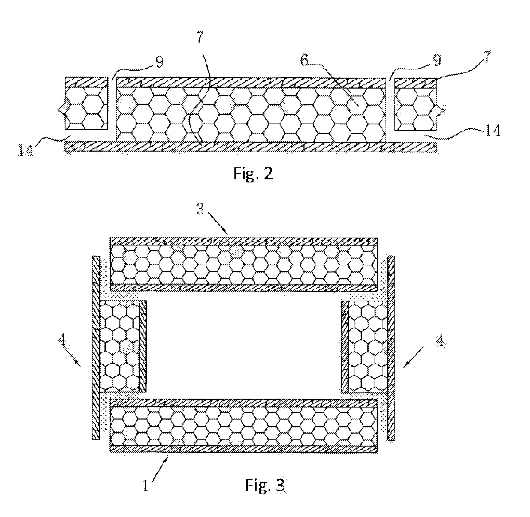
[0036]A fabrication process to connect branch ventilating ducts to main ventilating ducts, as shown in FIG. 1 (The steps within the broken lien frame don't apply to this example), includes following steps: Firstly, to fabricate air duct panels (namely non-combustible sandwich panels). Its production process is as follows: place an inorganic layer 7 (namely the substrate of the non-combustible sandwich panel) in the mould by mechanical rolling; put the selected insulation layer 6 (the non-combustible material layer in the middle of non-combustible sandwich panels) on top of the inorganic layer 7; place an inorganic layer 7 on top of the insulation layer 6; as the inorganic layer 7 solidifies here forms the non-combustible sandwich air duct panel (as shown in FIG. 2 and FIG. 3); then cut air duct panel and form the main air duct panel and the branch air duct panel through following procedures: firstly, cut air duct panels according to the designed size; Secondly, cut the two sid

Example

Example 2

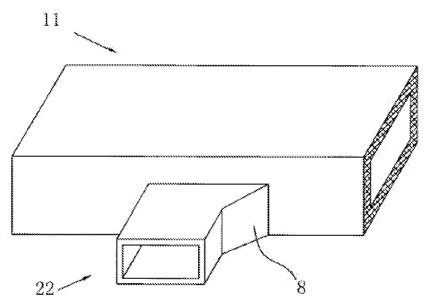
[0043]A fabrication process to connect branch ventilating ducts to main ventilating ducts, as shown in FIG. 5. In this example, the birdsmouth10 is located in the middle of one side plate of the main air duct11. The bonding faces of the birdsmouth are all of the right-angled flat shape. Four bonding faces of the connector21 are all of the right-angled flat shape as well. The connector21 are completed placed in the birdsmouth10 for the connection. Other processes are the same as Example 1.

Example

Example 3

[0044]A fabrication process to connect branch ventilating ducts to main ventilating ducts, as shown in FIG. 1 (exclusive of the steps within the broken lien frame), FIG. 6 and FIG. 7. In this example, the birdsmouth10 is located in the middle of one side plate of the main air duct11. The bonding faces of the birdsmouth are all of the right-angled flat shape. Four bonding faces of the connector21 are all of the right-angled ladder shape. The right-angled flat bonding faces are placed in the right-angled ladder-shaped bond faces for connection. The said adhesive is applied to the said right-angled ladder-shaped bonding faces. Other processes are the same as Example 1.


PUM

PropertyMeasurementUnit
Thicknessaaaaaaaaaa
Diameteraaaaaaaaaa

Abstract

A fabrication process to connect branch ventilating ducts to main ventilating ducts comprising: a, use non-combustible sandwich panels which are consisted by substrates on both sides and non-combustible material in middle to form a main air duct and a branch duct, both have rectangular cross-section; b, open on side panels of the main air duct birdsmouths (10) corresponding to a diameter of the branch air duct; c, attach a connector (21) on the branch duct to the birdsmouth (10). Therefore the manufactured air duct includes a connecting structure of a branch ventilating ducts with a main ventilating ducts, wherein in the main air duct (11) is located the birdsmouth (10) whose dimension is matching to the diameter of the branch air duct, and at the end of the branch air duct (22) is formed the connector (21).

Description


Claims


Application Information

Patent Timeline
Owner ZHI LIANG
Why Eureka
Try Eureka