Sealing multiwell plates

a multi-well plate and sealing technology, applied in the field of sealing multi-well plates, can solve the problems of inability to easily sterilize the roll of heat sealing material, unsatisfactory for some uses such as diagnostics or forensics, and the machine is both complex and costly. , to achieve the effect of avoiding contamination

Inactive Publication Date: 2012-03-08
4TITUDE
View PDF7 Cites 12 Cited by
  • Summary
  • Abstract
  • Description
  • Claims
  • Application Information

AI Technical Summary

Benefits of technology

The invention relates to an apparatus that can be used with sheets without having to handle them manually or automatically. This eliminates the risk of contaminating the sheet when handled manually.

Problems solved by technology

The technical problem addressed in this patent is how to provide a reliable and efficient mechanism for covering and closing a large number of wells on a plate without requiring complicated and expensive steps like extraction and heat sealing. Existing methods involve either manually or mechanically attaching a heat seal to the plate, which requires time and effort. There is also a concern over potential contaminants entering the plate's interior during the process.

Method used


Image

  • Sealing multiwell plates
  • Sealing multiwell plates
  • Sealing multiwell plates

Examples


Embodiment Construction

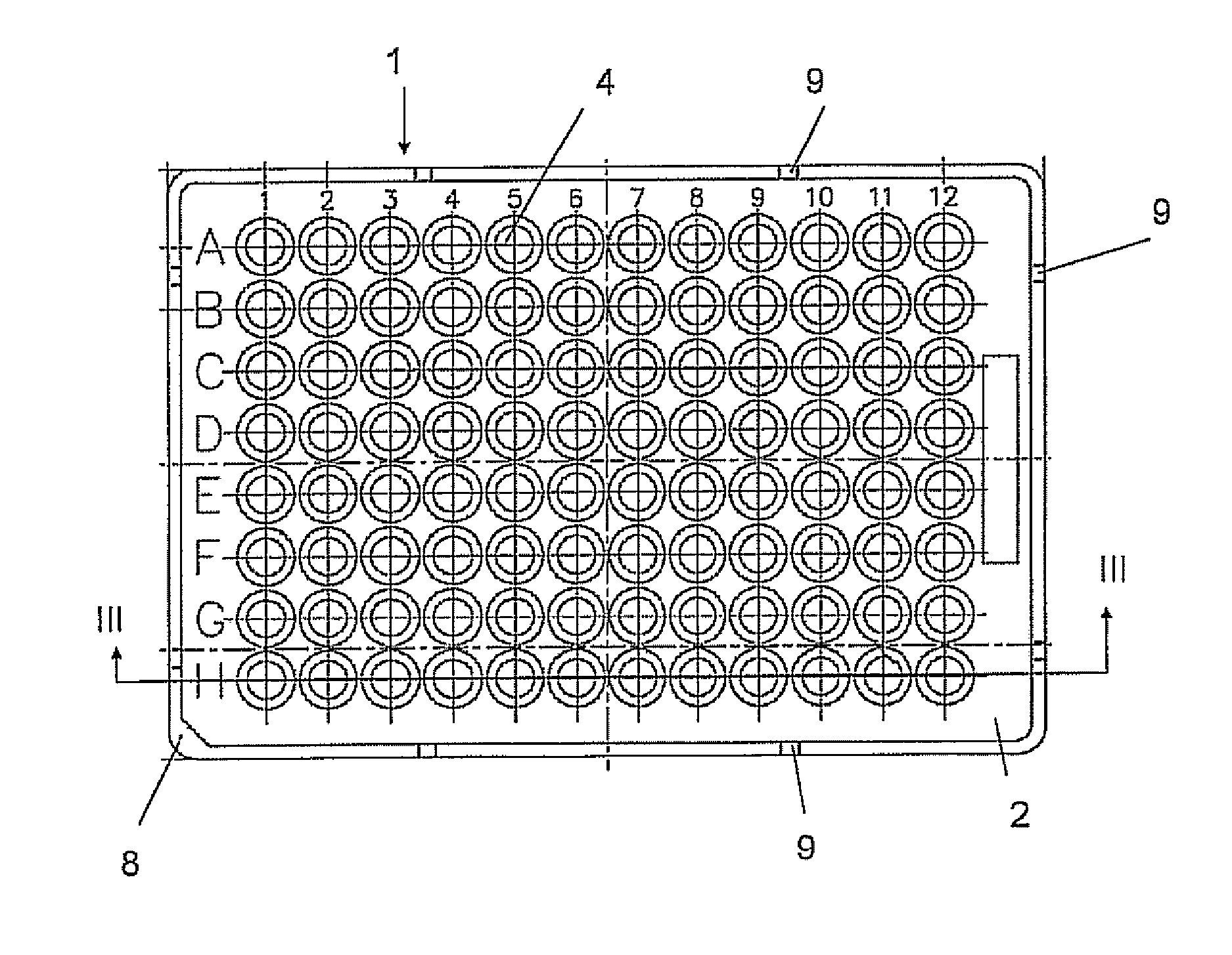
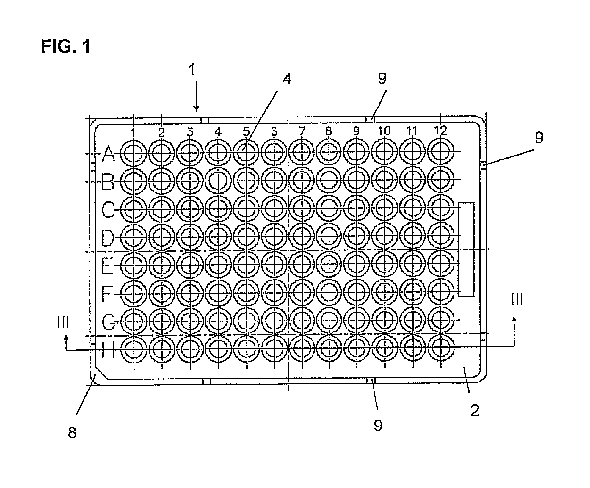
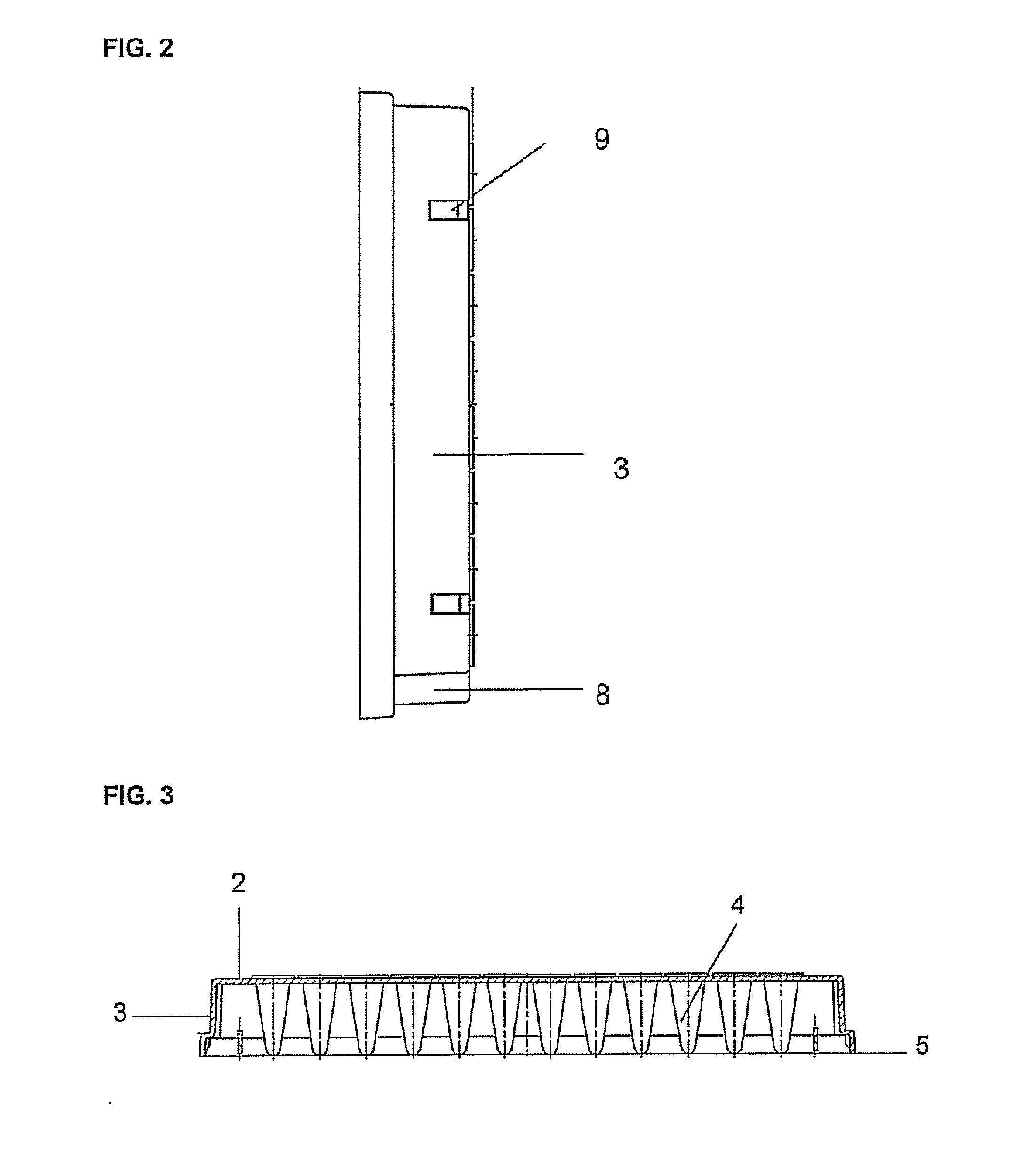
[0017]The multiwell plate 1, shown in FIGS. 1 to 4, comprises a plate 2 with an integral skirt 3, the plate mounting an array of individual thin walled wells 4. Lower edge 5 of skirt 3 is formed with an outwardly displaced rim 6, enabling the plates to be stacked one upon the other with the displaced rim fitting over the edge between plate 2 and skirt 3 of an underlying multiwell plate in the stack. The individual wells 4 are mounted in openings in the plate 2 with rims 7 extending above the surface of the plate 2. The plate has a chamfered corner region 8 and cut-outs 9 for indexing purposes. The design of multiwell plates is subject to a number of Standards, such as the SBS Standard, in order for multiwell plates from different manufacturers to be compatible with automatic plate handling apparatus, for example for performing the PCR (polymerase chain reaction) process; but persons skilled in this art will know that a number of variations are commonly encountered, including semi-skirt


PUM

PropertyMeasurementUnit
Heataaaaaaaaaa

Abstract

The present invention relates to a heat sealable member comprising a sheet of heat sealable material to a multiwell plate, wherein the sheet is mounted in a frame, and wherein said frame is sized to fit over a multiwell plate so that the sheet is contacted with at least one of the rims of the top of the plate and the individual wells; as well as to the use of the heat sealable member with automatic plate handling apparatus, especially in PCR processes. The present invention further relates to a method for sealing multiwell plates.

Description


Claims


Application Information

Patent Timeline
Owner 4TITUDE
Why Eureka
Try Eureka