Process of Forming Nano-Composites and Nano-Porous Non-Wovens
a technology of nano-porous non-wovens and composite materials, which is applied in the field of nano-composites and nano-porous non-wovens, can solve the problems of limited mechanical properties
- Summary
- Abstract
- Description
- Claims
- Application Information
AI Technical Summary
Benefits of technology
Problems solved by technology
Method used
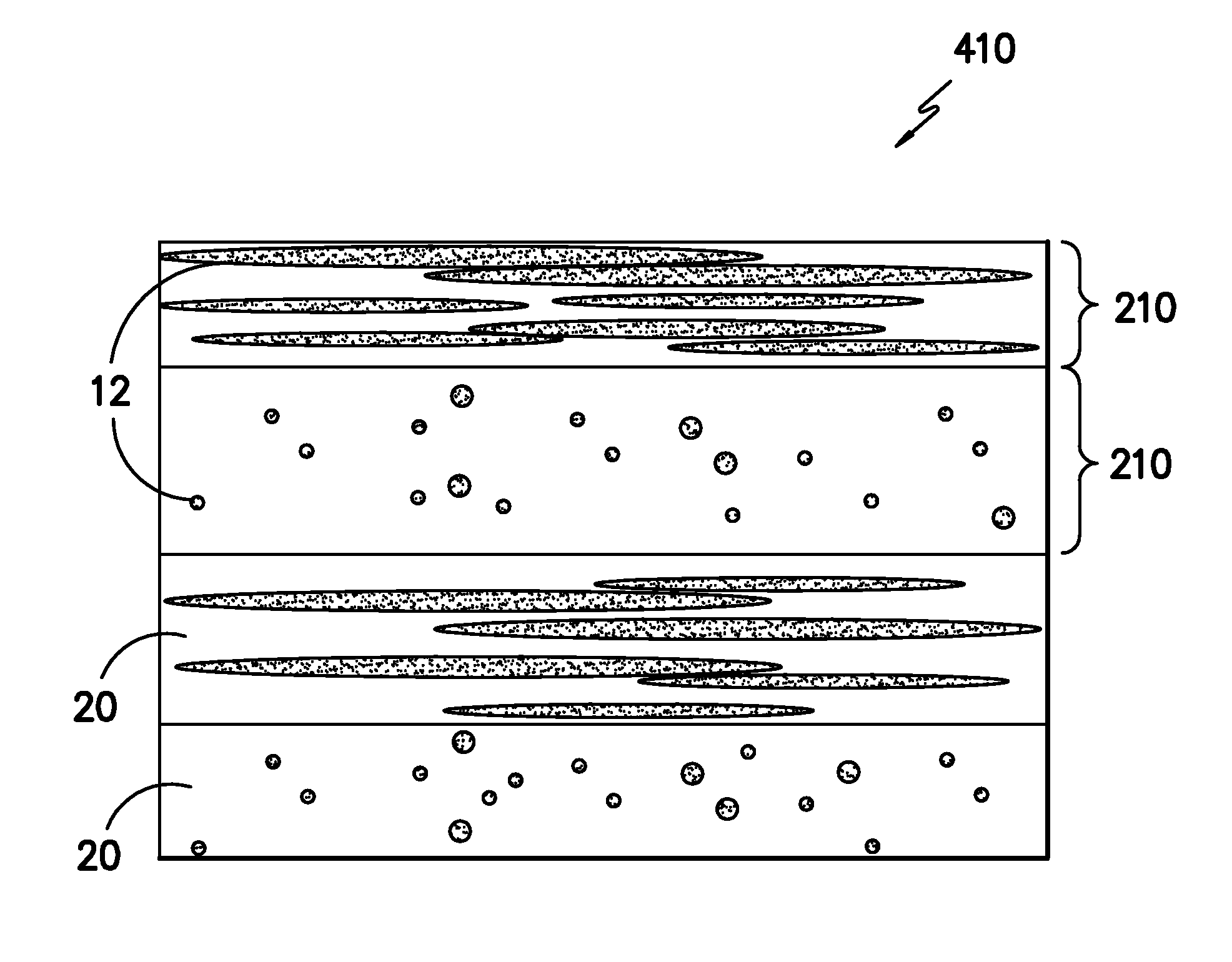
Image

Examples
example 1
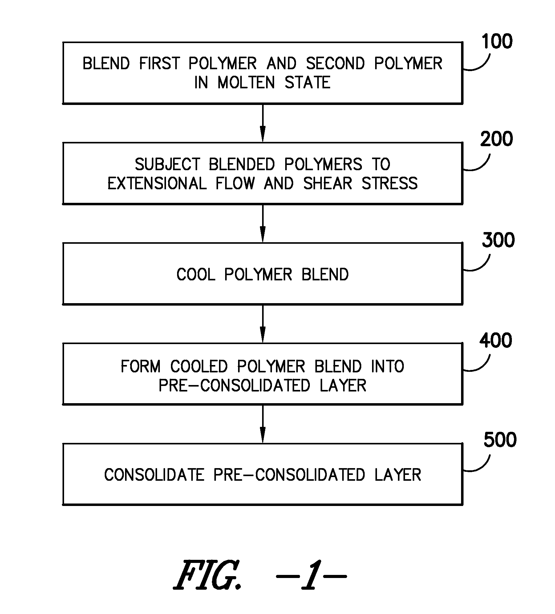
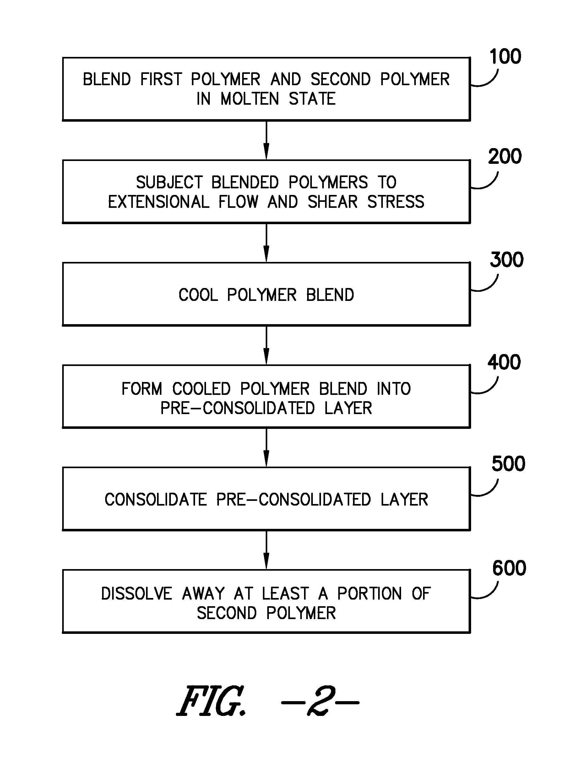
[0086]The first polymer was Homopolymer Polypropylene (HPP), obtained in granule form from Lyondell Basell as Pro-fax 6301 and had a melt flow of 12 g / 10 min (230° C., ASTMD 1238). The granule HPP was pelletized using a twin screw extruder Prism TSE 16TC. The second polymer was Cyrtal Polystyrene (PS), obtained in pellet form from Total Petrochemicals as PS 500 and had a melt flow of 14 g / 10 min (200° C., ASTMD 1238). The PS and HPP pellets were premixed in a mixer at a weight ratio of 80 / 20. The mixture was fed into a co-rotating 16 mm twin-screw extruder, Prism TSE 16TC. The feed rate was 150 g min−1 and the screw speed was 92 rpm. Barrel temperature profiles were 225, 255, 245, 240, and 235° C. The blend was extruded through a rod die where the extrudate was subject to an extensional force that was sufficient to generate nanofibrillar structure. The extrudate was cooled in a water bath at the die exit and collected after passing through a pelletizer. The pellets were the first
example 2
[0090]Example 2 was carried out with the same materials and process of Example 1, except that the consolidation temperature was 340° F. This consolidation temperature was 20° F. higher the melting point of HPP.
[0091]The morphology of the etched nano-composite article was observed using a SEM (FIG. 11A—1000× and FIG. 11B—10000×) represent the top view of the etched films. The nanofibers melted and fused into sheet like structure during consolidation and the nanofibers were destroyed. This consolidation temperature (at the given pressure and long resonance time) was proven to be too high to produce a nano-porous structure.
example 3
[0092]Example 3 was carried out with the same materials and process of Example 1, except that the consolidation temperature was 280° F. This consolidation temperature was 40° F. lower the melting point of HPP.
[0093]The morphology of the etched nano-composite article was observed using a SEM (FIG. 12A—1000×, FIG. 12B—10000×) represent the top view of the etched films. The nanofibers in the film were loosely connected and the film was very fragile to handle during testing indicating that less than 70% of the nanofibers were bonded to other nanofibers. This combination of consolidation temperature, pressure and resonance time was proven to be too low to produce nano-porous non-woven with good physical strength.
PUM
| Property | Measurement | Unit |
|---|---|---|
| Percent by volume | aaaaa | aaaaa |
| Percent by volume | aaaaa | aaaaa |
| Percent by volume | aaaaa | aaaaa |
Abstract
Description
Claims
Application Information
 - R&D Engineer
- R&D Manager
- IP Professional
- Industry Leading Data Capabilities
- Powerful AI technology
- Patent DNA Extraction
Browse by: Latest US Patents, China's latest patents, Technical Efficacy Thesaurus, Application Domain, Technology Topic.
© 2024 PatSnap. All rights reserved.Legal|Privacy policy|Modern Slavery Act Transparency Statement|Sitemap