Stator manufacturing method and stator
a manufacturing method and stator technology, applied in the field of stator manufacturing method, can solve problems such as increased cos
- Summary
- Abstract
- Description
- Claims
- Application Information
AI Technical Summary
Benefits of technology
Problems solved by technology
Method used
Image

Examples
first embodiment
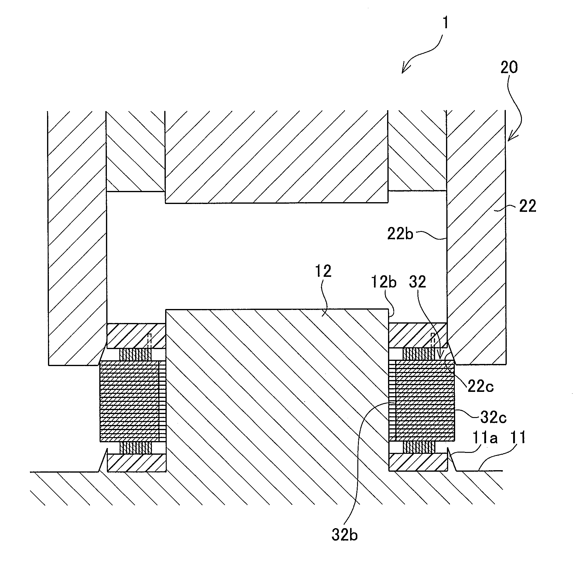
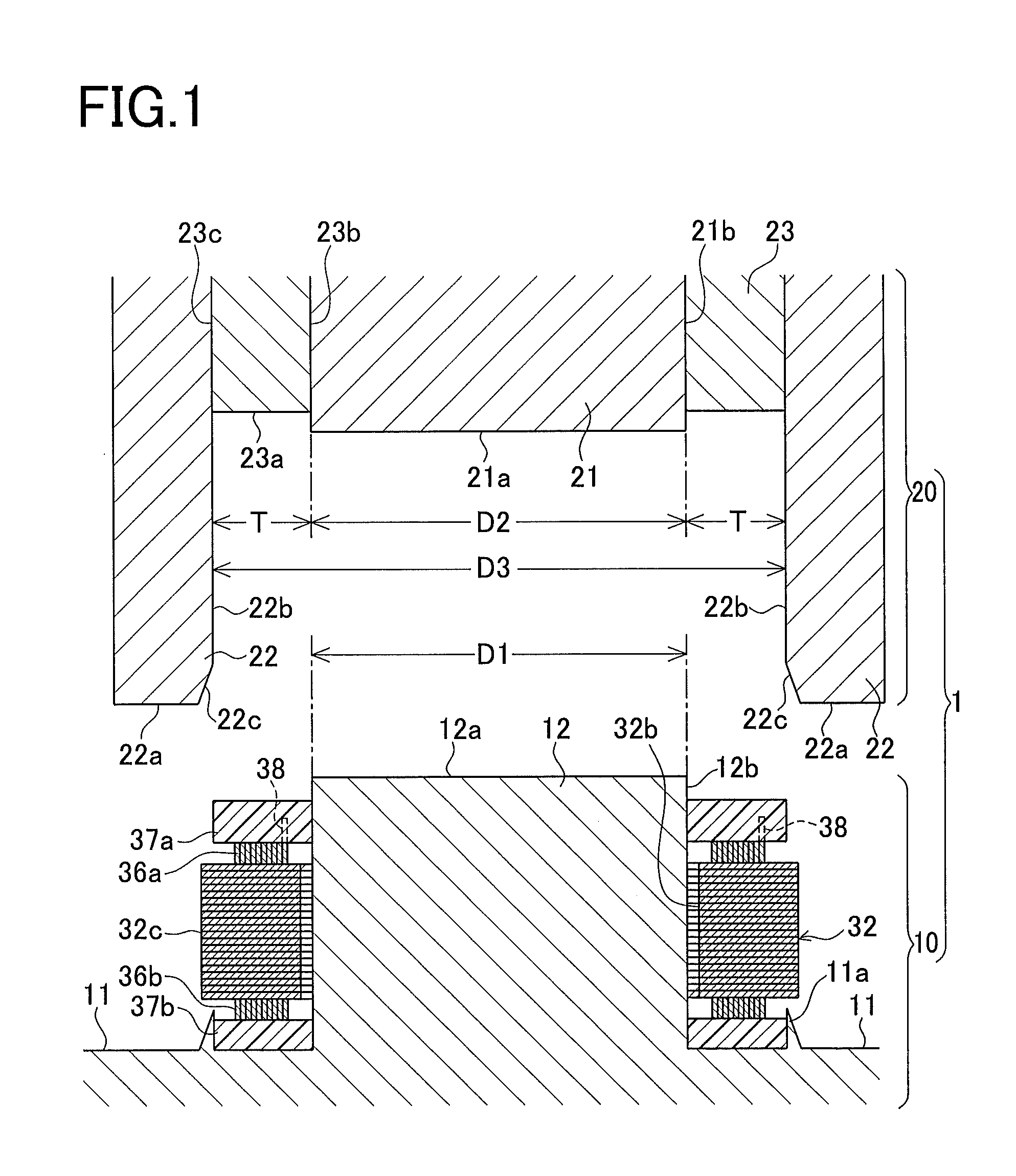
[0034]A schematic configuration of a stator manufacturing apparatus used in the first embodiment will be explained first referring to FIG. 1. FIG. 1 is a cross sectional view of the stator manufacturing apparatus in the first embodiment.
[0035]A stator manufacturing apparatus 1 includes a fixed mold 10 fixed on an apparatus side and a movable mold 20 placed to be movable as shown in FIG. 1. These molds 10 and 20 of the apparatus 1 are each internally provided with an (electromagnetic induction) heating device and a cooling channel, which are not shown.
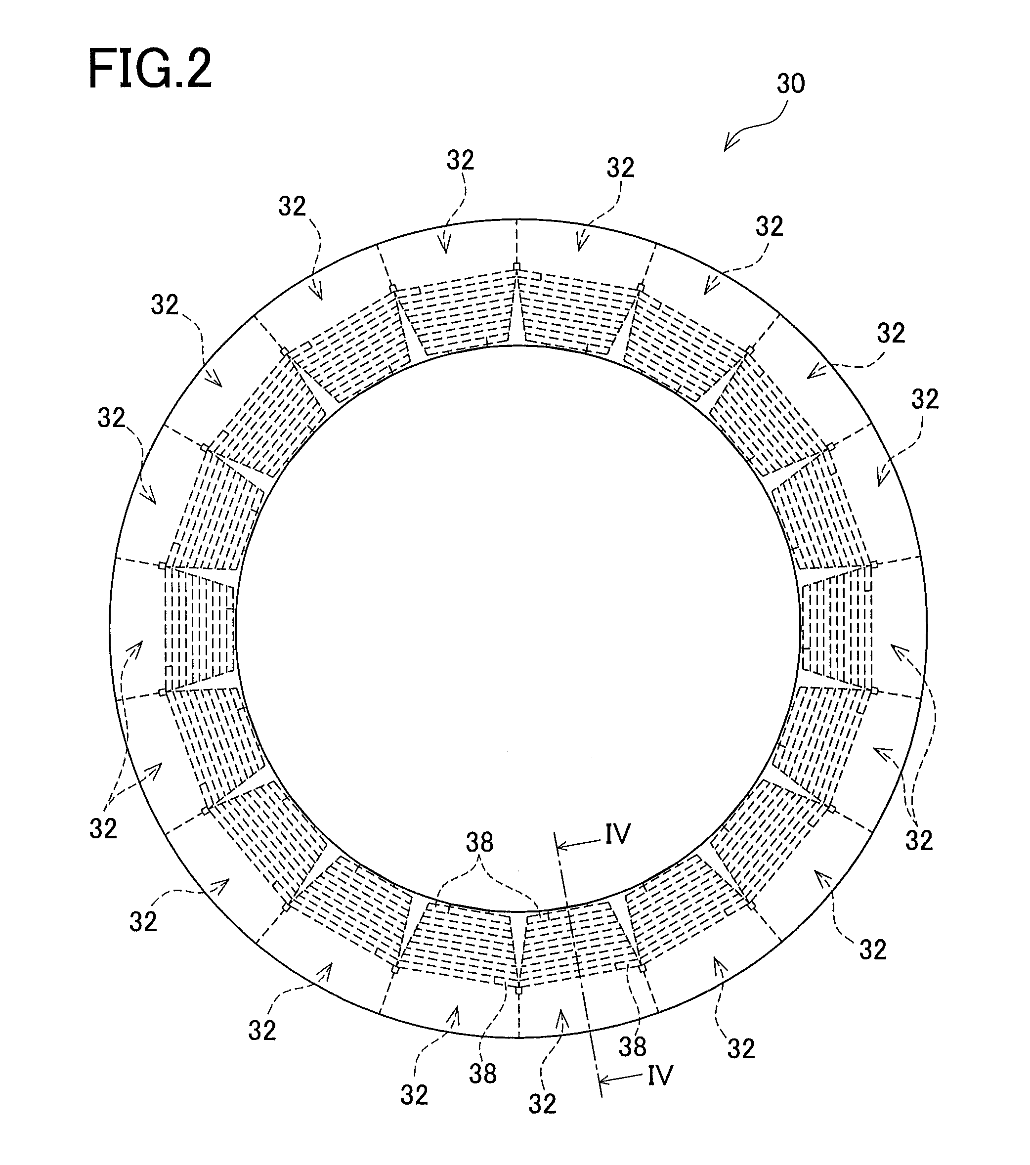
[0036]The fixed mold 10 includes a horizontal surface 11 formed to be horizontally flat and a columnar part 12 formed to protrude upward from the horizontal surface 11. This horizontal surface 11 is a support surface to support divided-core assemblies 32 from below.
[0037]The horizontal surface 11 is formed with a protrusion 11a protruding upward and extending along the outer periphery of the divided-core assemblies 32. The columnar part 12
first modified example
[0060]In a stator 40 of the first modified example, as shown in FIG. 10, grooves 44a and 44b each having a V-shaped cross section are formed to extend in an axial direction at the center of the outer periphery of a yoke 42 of each divided-core assembly 42. To be specific, the grooves 44a and 44b in the first modified example are the groove 44a formed on an upper end side of the yoke 44 in the axial direction and the groove 44b formed on a lower end side of the yoke 44 in the axial direction as shown in FIG. 11. These grooves 44a and 44b are molded with resin 45a and 45b that are the same material as the resin sheets 37a and 37b. The resin 45a molding or filling each groove 44a on the upper end side is integrally formed with the resin sheet 37a molding the upper coil end portions 36a. The resin 45b molding or filling each groove 44b on the lower end side is integrally formed with the resin sheet 37b molding the lower coil end portions 36b.
[0061]In the stator 40 of the first modified ex
second modified example
[0062]In a stator 50 of the second modified example, as shown in FIG. 12, a groove 54a having a V-shaped cross section is formed to extend in an axial direction at the center of the outer periphery of a yoke 54 of each divided-core assembly 52. Especially, the groove 54a of the second modified example, different from that in the first modified example, is formed continuously from an upper end side to a lower end side of the yoke 54 in the axial direction. This groove 54a is molded or filled with resin 55 that is the same material as the resin sheets 37a and 37b. An upper end portion 55a of the resin 55 filling the groove 54a is integrally formed with the resin sheet 37a molding the upper coil end portion 36a. Furthermore, a lower end portion 55b of the resin 55 filling the groove 54a is integrally formed with the resin sheet 37b molding the lower coil end portion 36b.
[0063]In the stator 50 of the second modified example, the upper end portion 55a of the resin 55 filling the groove 54a
PUM
| Property | Measurement | Unit |
|---|---|---|
| Length | aaaaa | aaaaa |
Abstract
Description
Claims
Application Information
 - R&D Engineer
- R&D Manager
- IP Professional
- Industry Leading Data Capabilities
- Powerful AI technology
- Patent DNA Extraction
Browse by: Latest US Patents, China's latest patents, Technical Efficacy Thesaurus, Application Domain, Technology Topic.
© 2024 PatSnap. All rights reserved.Legal|Privacy policy|Modern Slavery Act Transparency Statement|Sitemap