Method and system for measuring packet loss
- Summary
- Abstract
- Description
- Claims
- Application Information
AI Technical Summary
Problems solved by technology
Method used
Image

Examples
first embodiment
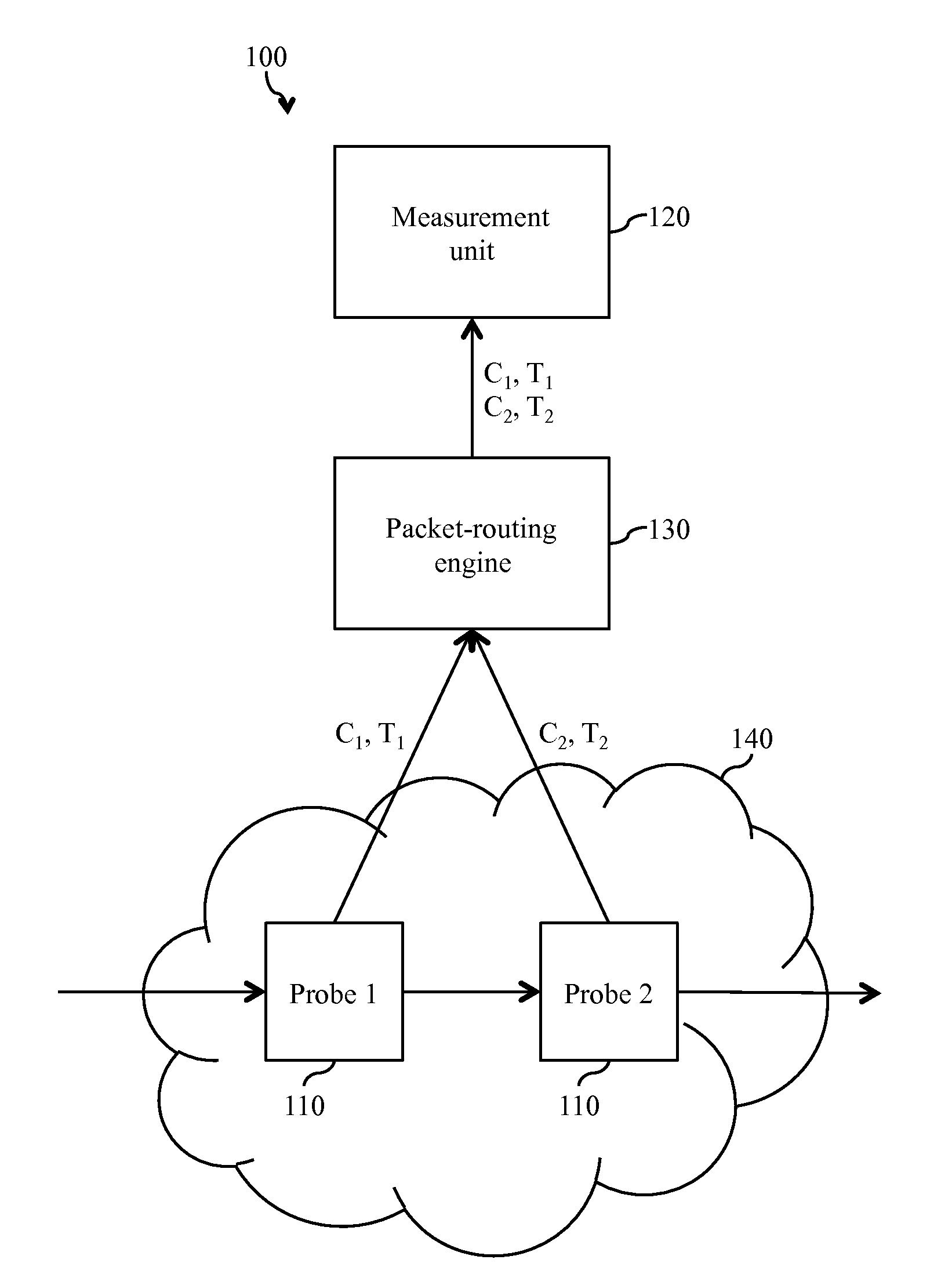
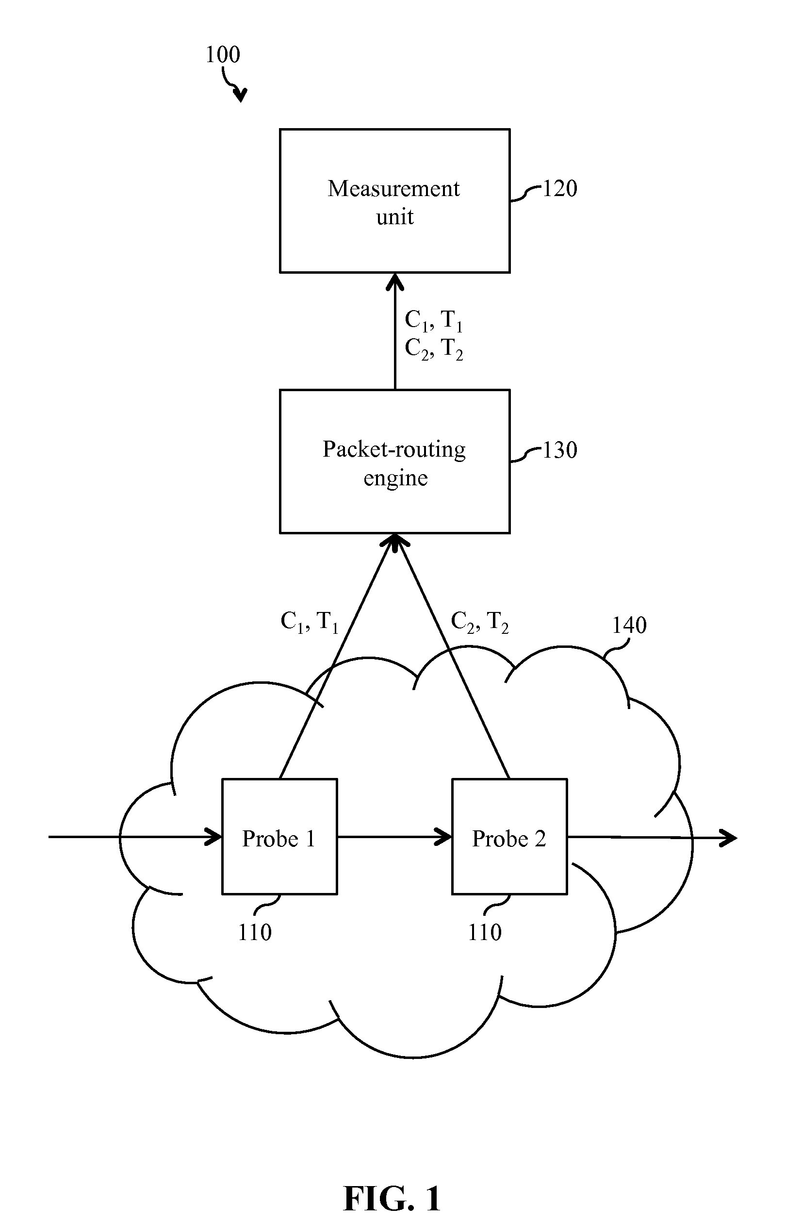
[0014]With reference to FIG. 1, a system 100 for measuring packet loss is used for passive measurements. The system 100 includes a plurality of probes 110, e.g., 2 to 500 probes, and a measurement unit 120. By way of example, a system 100 including two probes 110 is illustrated in FIG. 1. Optionally, the system 100 may also include a packet-routing engine 130.
[0015]The probes 110 are located at different locations in a network 140 under test, i.e., within the network 140 and / or at the edge of the network 140. The network 140 under test is a packet-based network and is, typically, Internet protocol (IP)-based. For example, the network 140 under test may be the Internet, a wide area network (WAN), a local area network (LAN), or a mobile network. Typically, the probes 110 are located at network nodes in the network 140 under test. For example, a probe 110 may be installed at a switch, a router, an access node, e.g., a digital subscriber line access multiplexer (DSLAM), a broadband remot
second embodiment
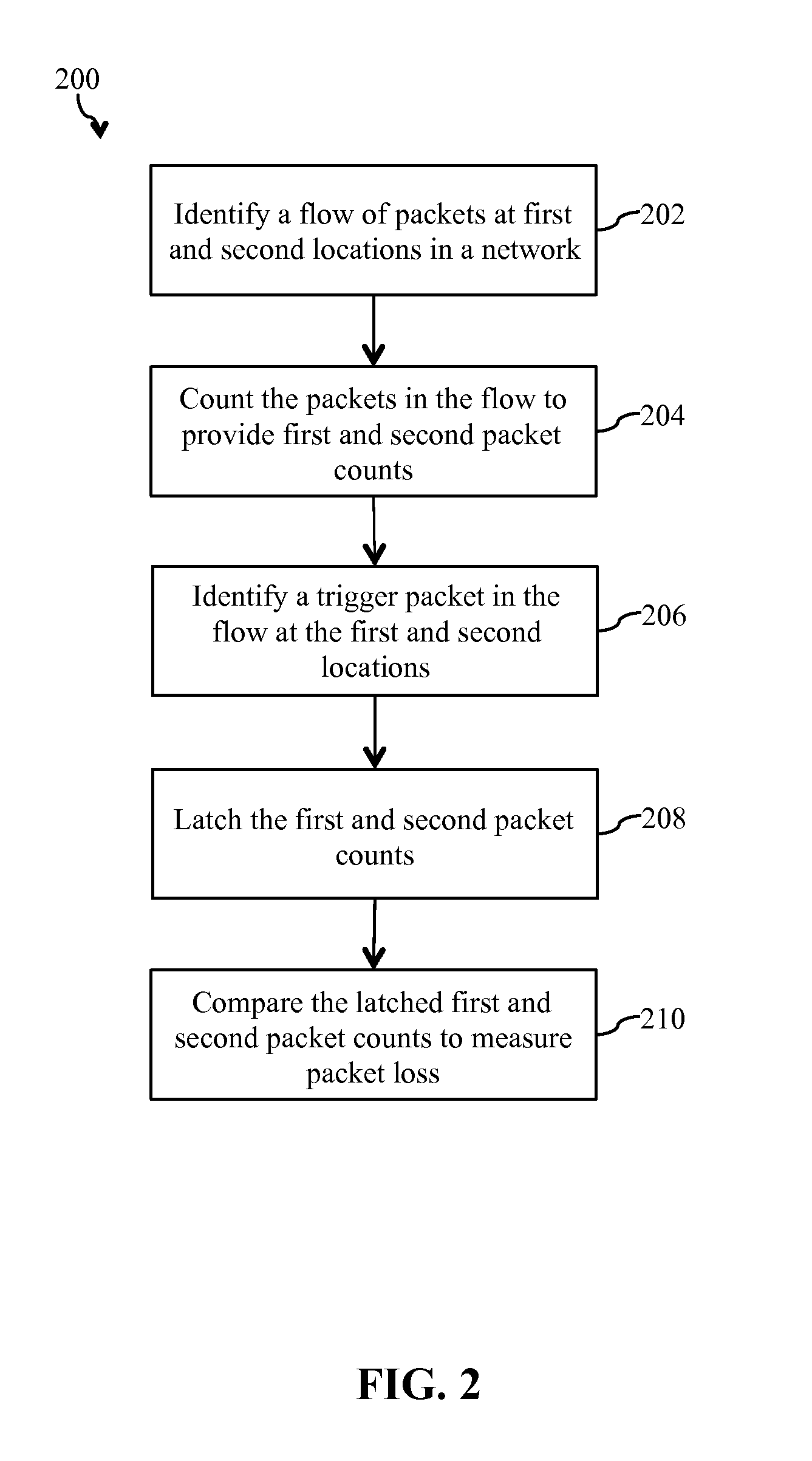
[0062]With reference to FIG. 4, a method 400 for measuring packet loss is used for active measurements and may be implemented using the system 300 of FIG. 3. At step 401, a flow of test packets is generated by the traffic generator 350. At step 402, the flow of test packets is identified at each of first and second locations in the network 140 under test, by first and second probes 110. At step 404, the test packets in the flow are counted at each of the first and second locations, by the first and second probes 110, to provide first and second packet counts, respectively. At step 406, a trigger packet, i.e., a predetermined test packet, in the flow is identified at each of the first and second locations, by the first and second probes 110. At step 408, the first and second packet counts are latched, by the first and second probes 110, upon identifying the trigger packet at each of the first and second locations, respectively, to provide latched first and second packet counts, which co
PUM
 Abstract
Description
Claims
Application Information
 - R&D Engineer
- R&D Manager
- IP Professional
- Industry Leading Data Capabilities
- Powerful AI technology
- Patent DNA Extraction
Browse by: Latest US Patents, China's latest patents, Technical Efficacy Thesaurus, Application Domain, Technology Topic.
© 2024 PatSnap. All rights reserved.Legal|Privacy policy|Modern Slavery Act Transparency Statement|Sitemap