Electronic module and method of manufacturing the same

a technology of electronic modules and manufacturing methods, applied in the direction of electrical apparatus contruction details, printed circuit non-printed electric components association, semiconductor/solid-state device details, etc., can solve the problems of high and rapid heat generation, dissipation of generated heat, and damage to the function of batteries and motors, and achieve low failure rate of electronic modules. , good operation

Active Publication Date: 2015-09-17
INFINEON TECH AG
View PDF2 Cites 2 Cited by
  • Summary
  • Abstract
  • Description
  • Claims
  • Application Information

AI Technical Summary

Benefits of technology

The technical effect that this invention solves by providing an electronics system with better performance over multiple temperatures or times while also reducing its risk of being damaged during use without losing functionality quickly enough.

Problems solved by technology

Technics relating to this patented technical problem addressed in the patented text involves how to prevent excessively strong electrical components like transistors generate too much heat that could damage them over time if they were located near certain locations within their protective casings.

Method used


Image

  • Electronic module and method of manufacturing the same
  • Electronic module and method of manufacturing the same
  • Electronic module and method of manufacturing the same

Examples


Embodiment Construction

[0018]In the following, further specific exemplary embodiments of the electronic module and the method of manufacturing the same will be explained. It should be noted that embodiments described in the context of the electronic module may also be combined with embodiments of the method of manufacturing the electronic module and vice versa.

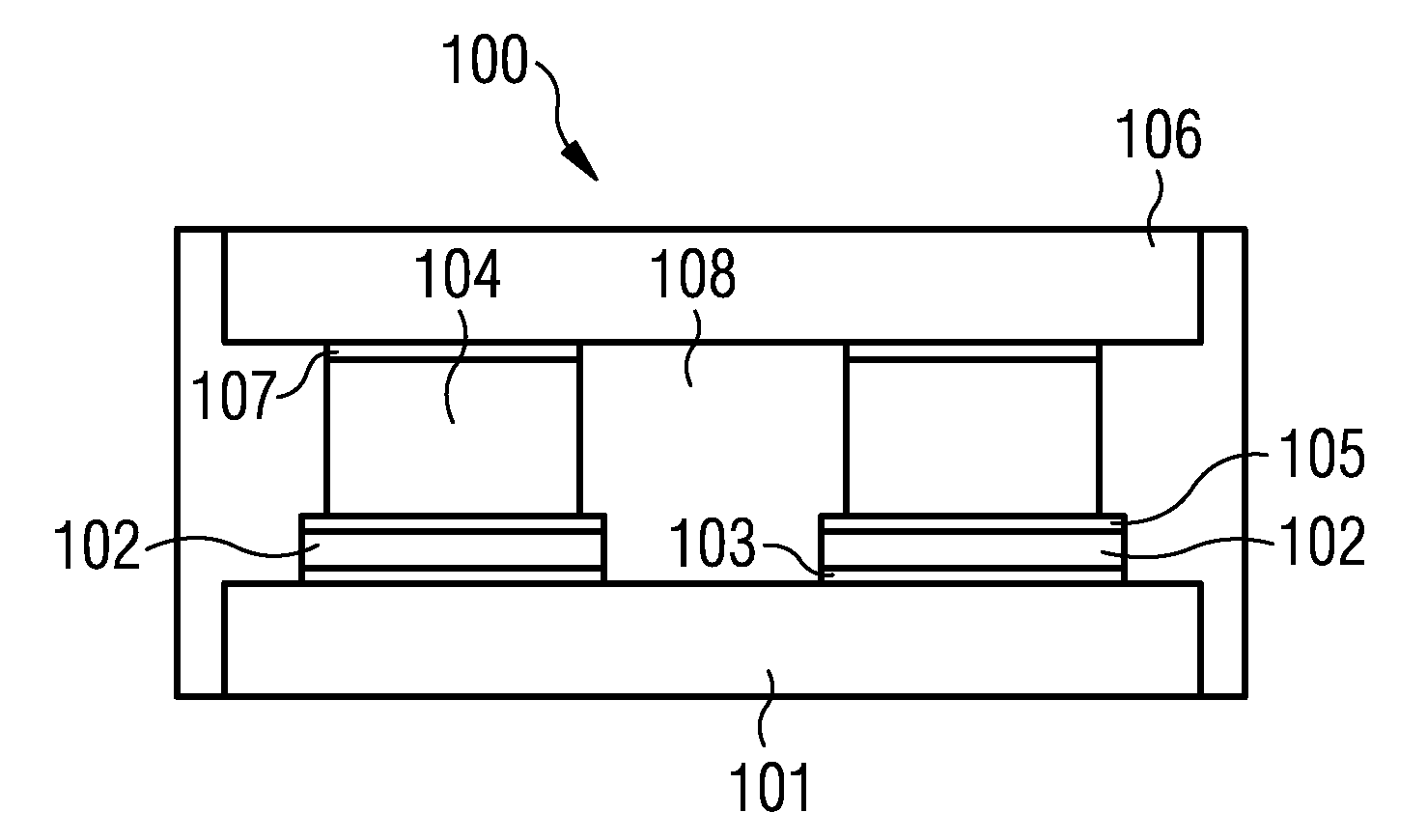
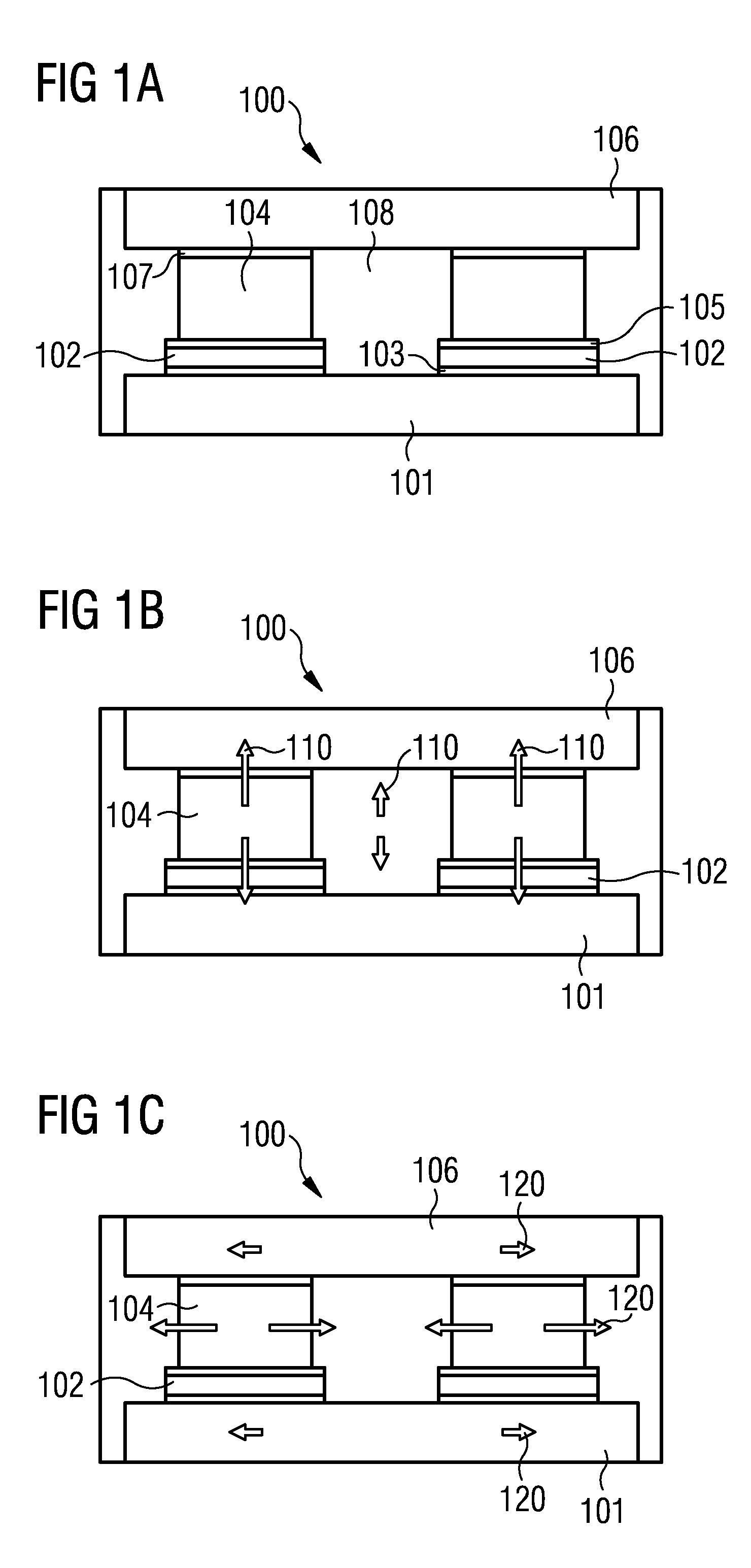
[0019]In particular, accordingly a gist of an exemplary embodiment may be seen in providing an electronic module comprising an electronic chip sandwiched between a first conductive board and a spacing element and an adjoining second conductive board, wherein the electronic module comprising a mold compound at least partially enclosing the electronic chip and the spacing element, wherein an coefficient of thermal expansion (CTE) of the spacing element is adapted to at least one coefficient of thermal expansions selected out of the group of coefficients of thermal expansion consisting of: a CTE of the first conductive board, a CTE of the second conductiv


PUM

PropertyMeasurementUnit
Fractionaaaaaaaaaa
Fractionaaaaaaaaaa
Fractionaaaaaaaaaa

Abstract

An electronic module is provided, which comprises a first carrier; an electronic chip comprising at least one electronic component and arranged on the first carrier; a spacing element comprising a surface arranged on the electronic chip and being in thermal conductive connection with the at least one electronic component; a second carrier arranged on the spacing element; and a mold compound enclosing the electronic chip and the spacing element at least partially; wherein the spacing element comprises a material having a CTE value being matched with at least one other CTE.

Description


Claims


Application Information

Patent Timeline
Owner INFINEON TECH AG
Why Eureka
Try Eureka