Zoom lens and image projection apparatus
- Summary
- Abstract
- Description
- Claims
- Application Information
AI Technical Summary
Benefits of technology
Problems solved by technology
Method used
Image

Examples
Example
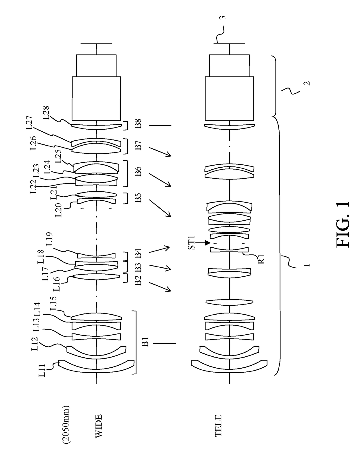
[0031]The zoom lenses of Embodiments 1 to 3 (except Embodiment 4) each include a front side fixed lens unit B1 (B21 and B31 in FIGS. 4 and 7) that is disposed on the enlargement conjugate side further than the front side movable lens units B2 to B4 and is fixed (unmoved) for the variation of magnification. The front side fixed lens unit is a first lens unit disposed at a most-enlargement conjugate side position in Embodiments 1 to 3.
[0032]Furthermore, the zoom lens of each embodiment includes at least two rear side movable lens units B5 to B7 (B25 and B26, B35 to B37, and B45 to B47 in FIGS. 4, 7, and 10) that are disposed on the reduction conjugate side further than the aperture stop ST1 and are movable for the variation of magnification.
[0033]Moreover, at least one of the at least three front side movable lens units includes at least one cemented lens (constituted by lenses L17 and L18 in FIG. 1). This makes it possible to reduce a variation in chromatic aberration of magnification f
Example
[0049]Description will be made of Embodiment 1 (Numerical example 1). FIG. 1 is a sectional view of a projection lens (whose projection distance 2050 mm) 60 using the zoom lens of Embodiment 1. The zoom lens 1 includes the following first to eighth lens units B1 to B8 disposed in order from the enlargement conjugate side to the reduction conjugate side.
[0050]The first lens unit B1 has a negative refractive power and is fixed for the variation of magnification. The second lens unit B2 has a positive refractive power and is moved for the variation of magnification. The third lens unit B3 has a positive refractive power and is moved for the variation of magnification. The fourth lens unit B4 has a negative refractive power and is moved for the variation of magnification. The fifth lens unit B5 has a positive refractive power and is moved for the variation of magnification. The sixth lens unit B6 has a positive refractive power and is moved for the variation of magnification. The seventh l
Example
Embodiment 2
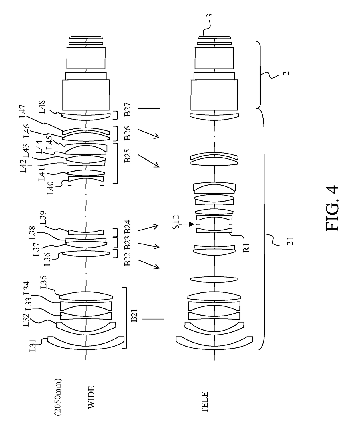
[0058]FIG. 4 is a sectional view of a projection lens (whose projection distance 2050 mm) using the zoom lens 21 of Embodiment 2 (Numerical example 2).
[0059]The zoom lens 21 includes the following first to seventh lens units B21 to B27 disposed in order from the enlargement conjugate side to the reduction conjugate side. This embodiment includes two rear side movable lens units whose number is smaller than that of Embodiment 1.
[0060]The first lens unit B21 has a negative refractive power and is fixed for the variation of magnification. The second lens unit B22 has a positive refractive power and is moved for the variation of magnification. The third lens unit B23 has a positive refractive power and is moved for the variation of magnification. The fourth lens unit B24 has a negative refractive power and is moved for the variation of magnification. The fifth lens unit B25 has a positive refractive power and is moved for the variation of magnification. The sixth lens unit B26
PUM
 Abstract
Description
Claims
Application Information
 - R&D Engineer
- R&D Manager
- IP Professional
- Industry Leading Data Capabilities
- Powerful AI technology
- Patent DNA Extraction
Browse by: Latest US Patents, China's latest patents, Technical Efficacy Thesaurus, Application Domain, Technology Topic.
© 2024 PatSnap. All rights reserved.Legal|Privacy policy|Modern Slavery Act Transparency Statement|Sitemap