Fluid handling device
a technology of a handling device and a liquid, which is applied in the direction of laboratory glassware, instruments, chemistry apparatus and processes, etc., can solve the problems of difficult to accurately determine the amount of dna or rna fragments, the device used in the method is more likely to become large, and the work is complicated. to achieve the effect of reducing the amount of liquid to be used
- Summary
- Abstract
- Description
- Claims
- Application Information
AI Technical Summary
Benefits of technology
Problems solved by technology
Method used
Image

Examples
embodiment 1
[0022](Configuration of Fluid Handling Device)
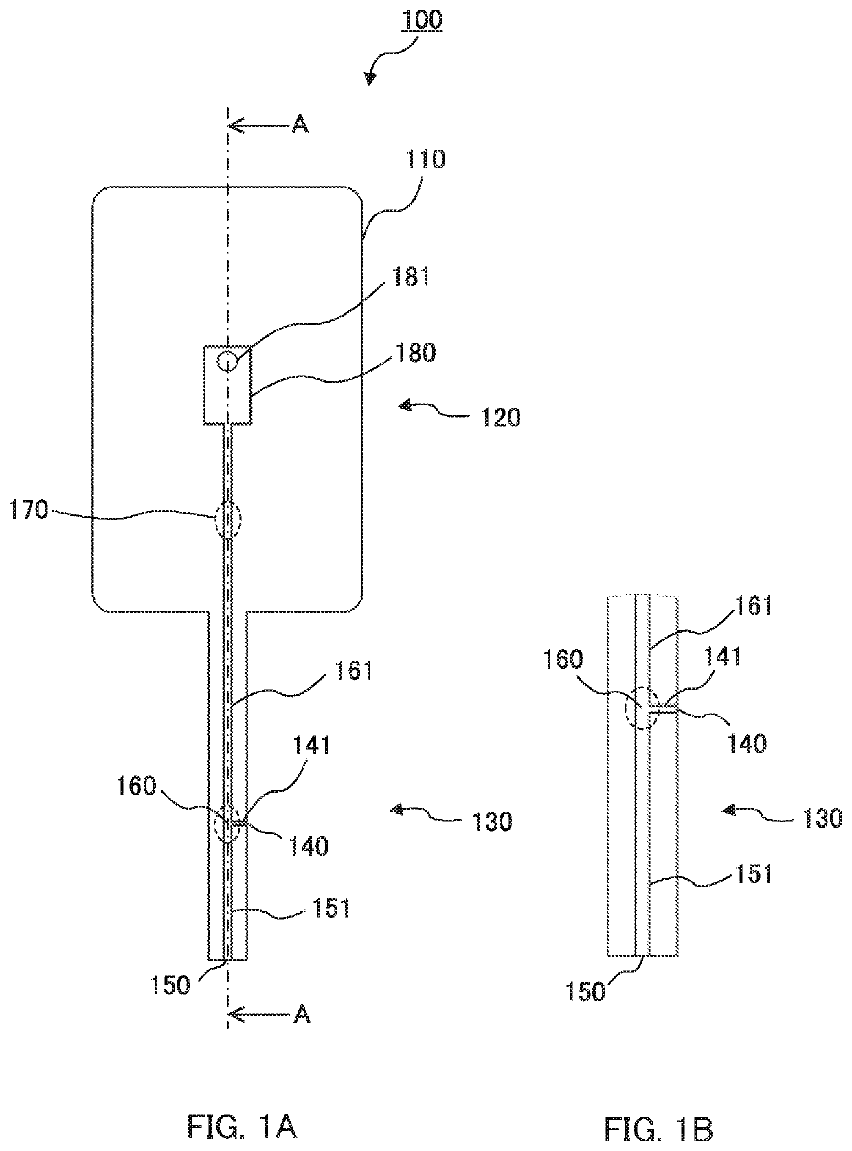
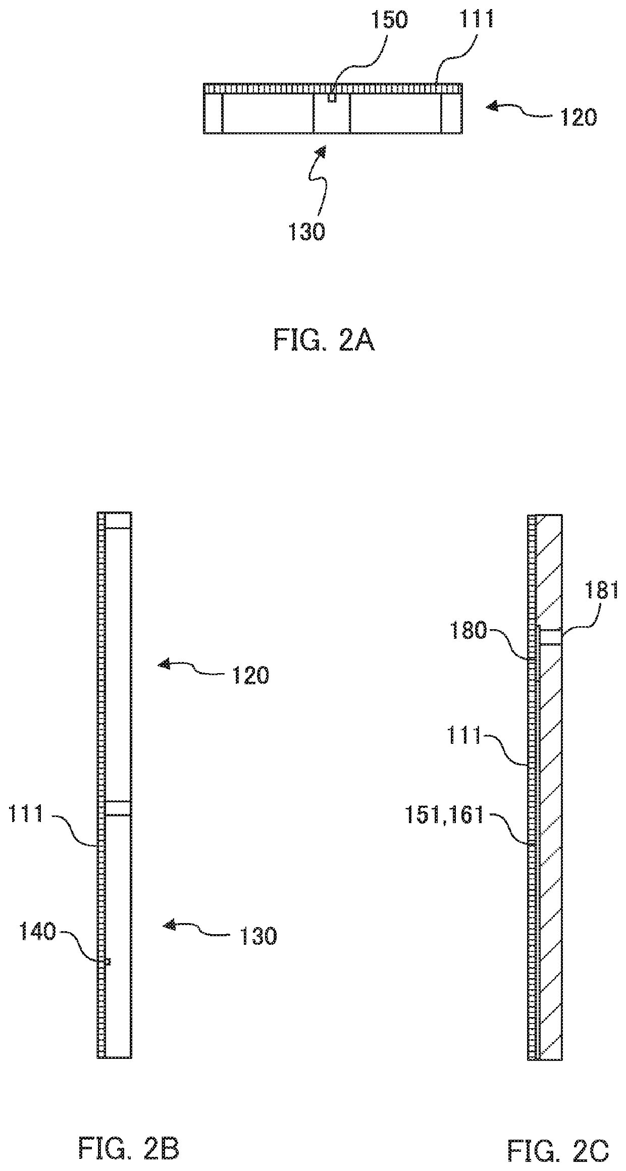
[0023]FIGS. 1A to 2C illustrate fluid handling device 100 according to embodiment 1 of the present invention. FIG. 1A is a plan view of fluid handling device 100. FIG. 1B is a partially enlarged view of immersion part 130 of fluid handling device 100. FIGS. 1A and 1B omit film 111 to show the structure of the channels inside. FIG. 2A is a front view of fluid handling device 100. FIG. 2B is a right side view of fluid handling device 100. FIG. 2C is a cross-sectional view taken along line A-A of FIG. 1A.
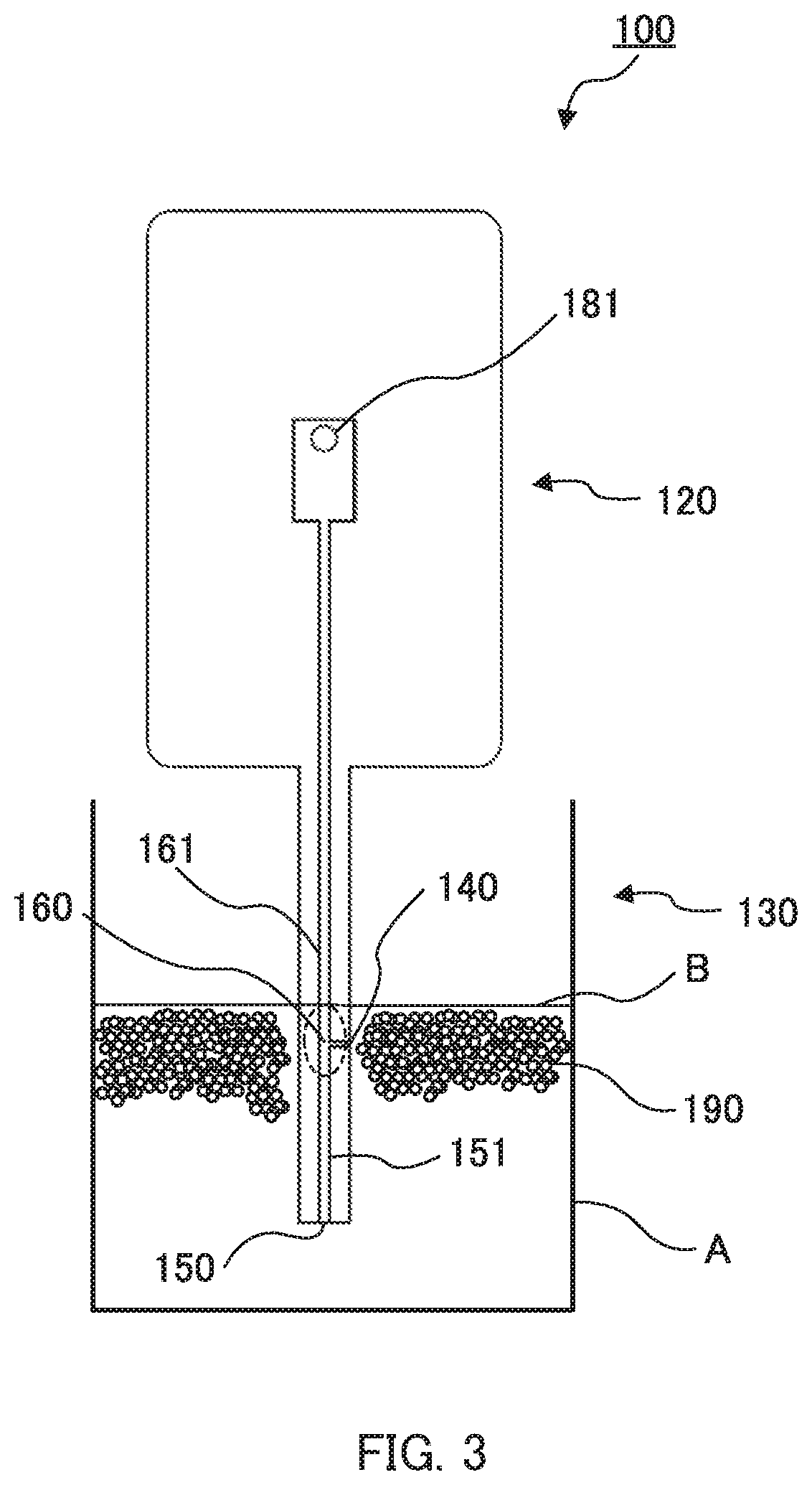
[0024]Fluid handling device 100 is for, from a mixed liquid in which particles 190 are gathered in a surface layer or a bottom layer in a liquid, arranging particles 190 in a line and allowing particles 190 to flow while separating particles 190 from each other (see FIG. 4). In addition, fluid handling device 100 can also measure various information (for example, presence / absence of amplification of DNA in the droplet) for each of particles
embodiment 2
[0049](Configuration of Fluid Handling Device)
[0050]Fluid handling device 200 according to embodiment 2 differs from fluid handling device 100 according to embodiment 1 only in that fluid handling device 200 further includes particle guiding channel 210. The same components as those of fluid handling device 100 according to embodiment 1 are designated by the same reference numerals, and the description thereof will be omitted.
[0051]FIG. 5 is a plan view of fluid handling device 200 including particle guiding channel 210. FIG. 5 omits film 111 to show the structure of the channels inside. FIG. 6A is a cross-sectional view taken along line B-B of FIG. 5. FIG. 6B is a right side view of fluid handling device 200. FIG. 6C is a cross-sectional view taken along line A-A of fluid handling device 200. As illustrated in FIGS. 5 to 6C, particle intake port 140 is disposed so as to be located above liquid intake port 150 in a liquid in fluid handling device 200 according to the present embodiment
embodiment 3
[0058](Configuration of Fluid Handling Device and Method for Using Fluid Handling Device)
[0059]Fluid handling device 300 according to embodiment 3 differs from fluid handling device 200 according to embodiment 2 only in the configuration of particle guiding channel 320. The same components as those of fluid handling apparatus 100 according to embodiment 1 or fluid handling apparatus 200 according to embodiment 2 are designated by the same reference numerals, and the description thereof will be omitted.
[0060]FIG. 8 is a partially enlarged view illustrating the configuration and usage state of fluid handling device 300. As illustrated in FIG. 8, film 310 is bonded to one of the surfaces of substrate 110 in fluid handling device 300 according to the present embodiment, but a part of film 310 is not bonded to substrate 110 and protrudes at the tip portion of immersion part 130. More specifically, film 310 protrudes from substrate 110 in a region, at the side surface (right side surface) wh
PUM
 Abstract
Description
Claims
Application Information
 - R&D Engineer
- R&D Manager
- IP Professional
- Industry Leading Data Capabilities
- Powerful AI technology
- Patent DNA Extraction
Browse by: Latest US Patents, China's latest patents, Technical Efficacy Thesaurus, Application Domain, Technology Topic.
© 2024 PatSnap. All rights reserved.Legal|Privacy policy|Modern Slavery Act Transparency Statement|Sitemap