Support unit and apparatus for treating substrate

a technology for supporting units and substrates, applied in electrical apparatus, basic electric elements, electric discharge tubes, etc., can solve problems such as uniformity in substrate treatment, and achieve the effects of improving the treatment efficiency of the edge region, and reducing the number of substrates

Pending Publication Date: 2022-06-23
SEMES CO LTD
View PDF0 Cites 0 Cited by
  • Summary
  • Abstract
  • Description
  • Claims
  • Application Information

AI Technical Summary

Benefits of technology

The device described in this patents allows for efficient processing of semiconductor wafers with improved surface area utilization compared to previous methods that were less effective at improving overall performance or even worse than older techniques such as etchants. This can lead to better quality products being produced more effectively on these types of wafer surfaces. Additionally, there are other technical benefits like enhanced process stability during manufacturing processes due to reduced temperature variations caused by heated components within the system itself. Overall, this technology enhances productivity while reducing costs associated with current technologies used in fabrication.

Problems solved by technology

The technical problem addressed in this patented technology relates how evenly distributed plasmas are delivered onto wafers during various processes used on them (etching, cleaning). This can lead to non-uniformities affecting the quality of processing results from these methods.

Method used


Image

  • Support unit and apparatus for treating substrate
  • Support unit and apparatus for treating substrate
  • Support unit and apparatus for treating substrate

Examples


Embodiment Construction

[0041]Hereinafter, an exemplary embodiment of the present invention will be described more fully hereinafter with reference to the accompanying drawings, in which exemplary embodiments of the invention are shown. However, the present invention can be variously implemented and is not limited to the following exemplary embodiments. In the following description of the present invention, a detailed description of known functions and configurations incorporated herein is omitted to avoid making the subject matter of the present invention unclear. In addition, the same reference numerals are used throughout the drawings for parts having similar functions and actions.

[0042]Unless explicitly described to the contrary, the term of “including” any component will be understood to imply the inclusion of stated elements but not the exclusion of any other elements. In the present application, it should be understood that term “including” or “having” indicates that a feature, a number, a step, an ope


PUM


Abstract

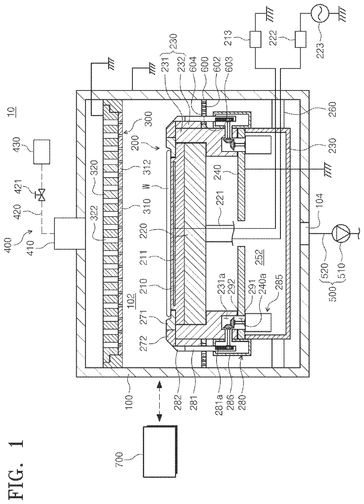
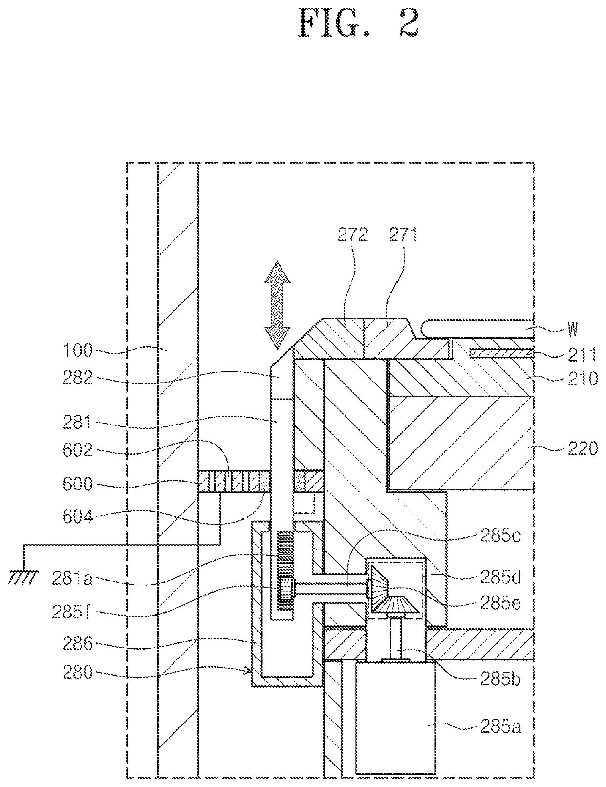
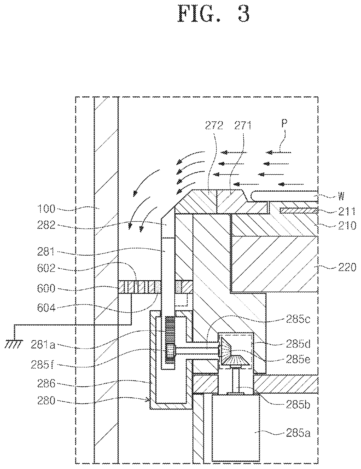
Provided is a support unit included in an apparatus for treating a substrate using plasma and configured to support the substrate. The support unit may include a power supply rod connected to a high-frequency power supply; an electrode plate configured to receive power from the power supply rod; and a ground ring provided to surround the electrode plate when viewed from the top and including a ground ring to be grounded.

Description


Claims


Application Information

Patent Timeline
Owner SEMES CO LTD
Why Eureka
Try Eureka