Nonaqueous electrochemical cell with improved energy density

Inactive Publication Date: 2005-02-01
ENERGIZER BRANDS
View PDF14 Cites 267 Cited by
  • Summary
  • Abstract
  • Description
  • Claims
  • Application Information

AI Technical Summary

Problems solved by technology

There are however many challenges in achieving a commercially viable cell with this particular electrochemical couple.
One key challenge is how to use internal cell volume efficiently.
It is known that this electrochemical system results in a volume increase upon discharge and the accompanying formation of reaction products.
Attempts to improve the energy density of the cell by increasing the density of the cathode present additional challenges.
Further, the densification of the cathode through an increase in the calendering force applied to the coated electrode stock can result in a stretching of the metallic foil substrate that

Method used


Image

  • Nonaqueous electrochemical cell with improved energy density
  • Nonaqueous electrochemical cell with improved energy density

Examples


example

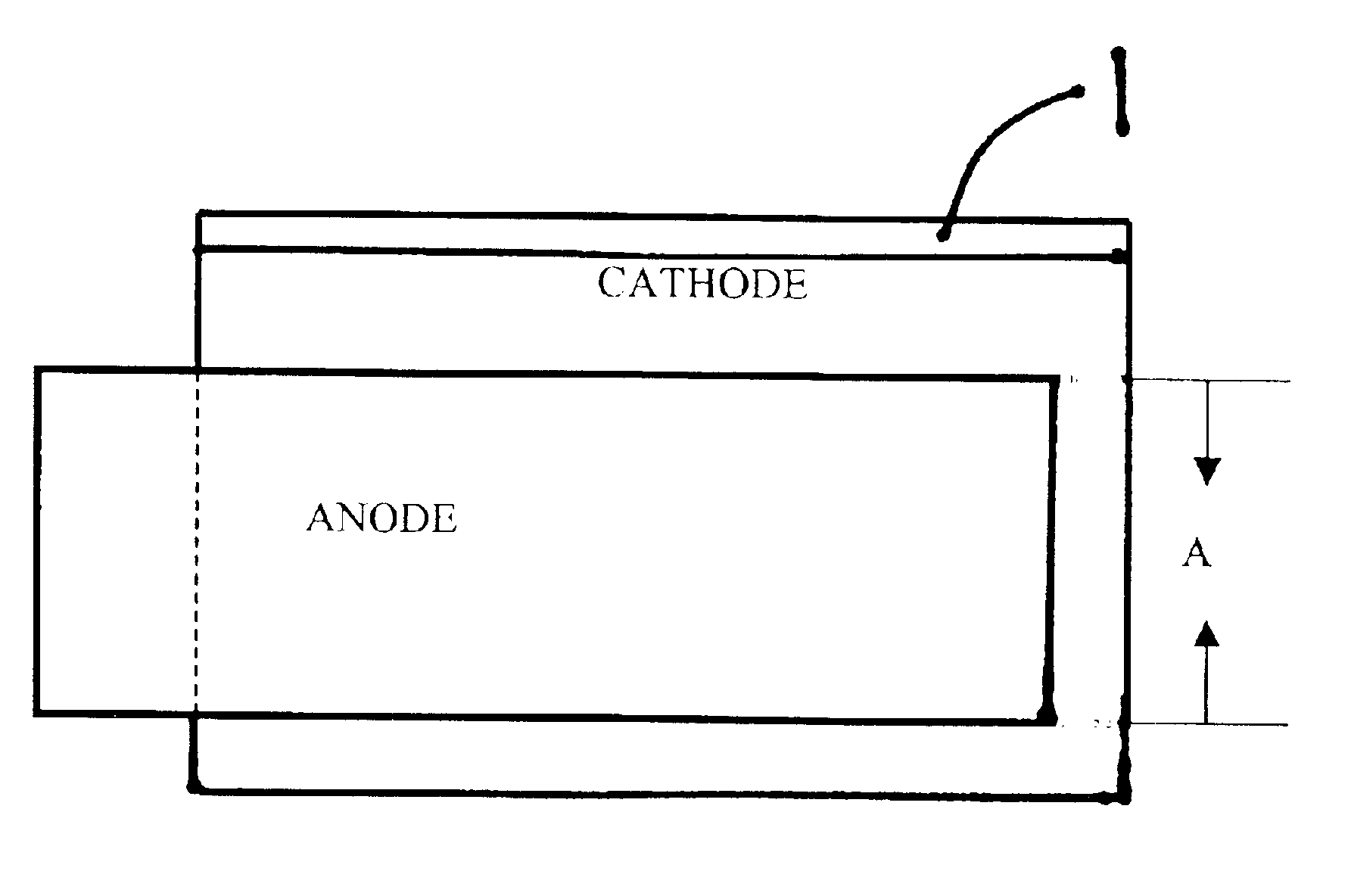
An electrochemical cell comprising lithium as the active anode material and pyrite as the active cathode material is constructed as follows. A continuous strip of lithium metal foil 0.006 inches thick by 1.535 inches wide and alloyed at 0.5 weight percent with aluminum is provided. An aluminum cathode current collector continuous strip 0.001 inches thick by 1.72 inches wide is provided. The aluminum cathode collector strip is full hard standard alloy 1145-H19 aluminum and both surfaces are flame cleansed to remove oils and improve adhesion of the coating to the substrate surface.

A cathode coating slurry is prepared using the following solids:

WeightMaterialpercent (dry)cm3 / 100 gmsFeS292.019.087Acetylene black1.40.733Highly crystalline synthetic graphite4.01.777Fumed silica0.30.136Micronized PTFE0.30.136Kraton2.02.19824.067 cm3 / 100 gms4.155 gm / cm3

Battery grade iron pyrite with a purity level of 95 percent by weight available from Chemetall is sieved through a 230 mesh screen to rem


PUM


Abstract

This invention relates to a nonaqueous cell comprising a lithium metallic foil anode and a cathode coating comprising iron disulfide as the active material wherein the coating is applied to at least one surface of a metallic substrate that functions as the cathode current collector. In particular, the cell of the within invention has improved performance on high rate discharge and is achieved, surprisingly, with an anode underbalance. The cell of the within invention has an anode to cathode input that is less than or equal to 1.0. We have discovered, unexpectedly, that the energy density for the cell both volumetrically and gravimetrically can be improved by approximately 20 to 25% while only increasing the volume of the cathode coating solids by approximately 10% through a unique and novel cathode coating formulation used in conjunction with an alloyed lithium foil.

Description


Claims


Application Information

Patent Timeline
Owner ENERGIZER BRANDS
Why Eureka
Try Eureka