Spin-valve type thin film magnetic element having bias layers and ferromagnetic layers
a thin film magnetic element, spin-valve technology, applied in the direction of nanoinformatics, magnetic bodies, instruments, etc., can solve the problems of irregular magnetic recording pattern recorded on the magnetic recording medium, and achieve the effect of preventing magnetic recording errors, good heat resistance, and high reliability
- Summary
- Abstract
- Description
- Claims
- Application Information
AI Technical Summary
Benefits of technology
Problems solved by technology
Method used
Image

Examples
first embodiment
[First Embodiment]
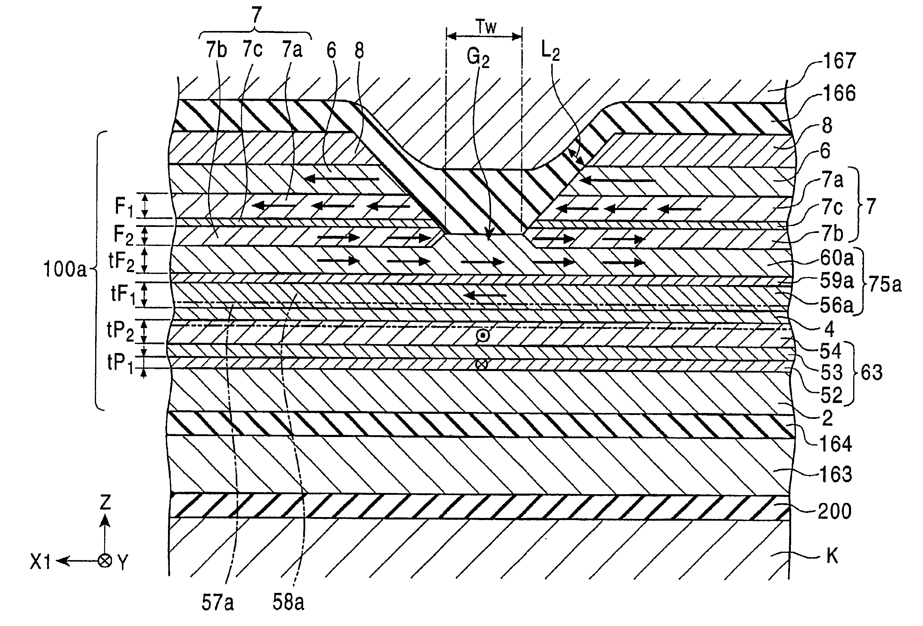
FIG. 1 shows a cross section of the structure of the spin-valve type thin film magnetic element in the first embodiment of the present invention viewed from the opposed face side to the recording medium. FIGS. 2 and 3 show a thin film magnetic head comprising the spin-valve type thin film magnetic element according to the present invention.
Shield layers are formed on and under the spin-valve type thin film magnetic element 1 according to the present invention separated by gap layers. A regenerative GMR head h1 is composed of the spin-valve type thin film magnetic element, the gap layers and the shield layers.
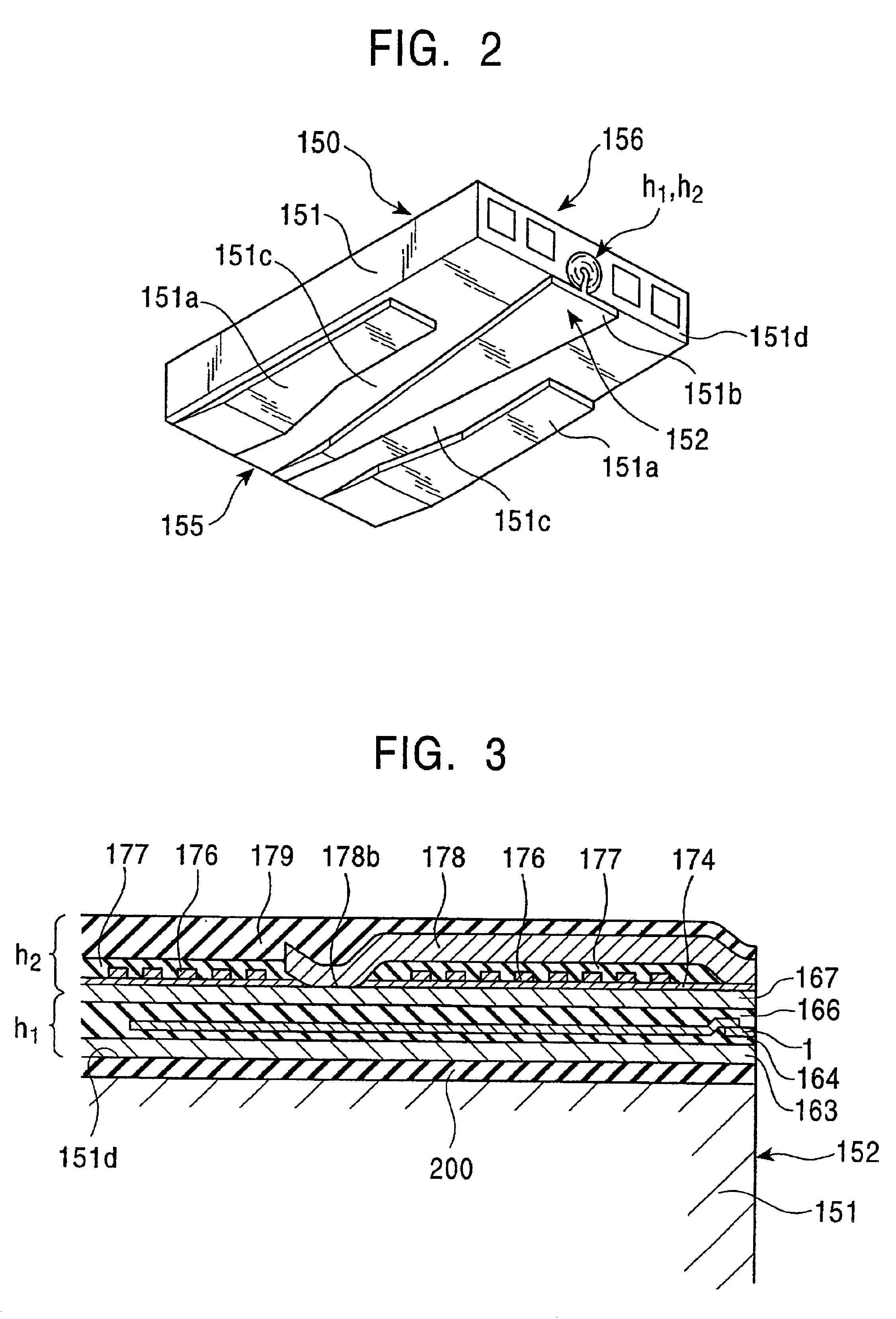
A recording inductive head h2 may be laminated on the regenerative GMR head h1.
The GMR head h1 comprising the spin-valve type thin film magnetic element 1 is provided at the trailing side 151d of a slider 151 together with the inductive head h2, and constitutes a thin film magnetic head 150 to enable sensing of a recorded magnetic field from a magnetic recording m
second embodiment
[Second Embodiment]
FIG. 4 is a vertical cross section illustrating the spin-valve type thin film magnetic element according to the second embodiment of the present invention. FIG. 5 is a cross section showing the structure of the spin-valve type thin film magnetic element shown in FIG. 4 viewed from the opposed face side to the recording medium.
This spin-valve type thin film magnetic element 100 is, like the spin-valve type thin film magnetic element 1 shown in FIG. 1, attached at the end of the trailing side 151d of the floating type slider 151 provided in the hard disk device, and senses the recorded magnetic field of the hard disk.
The magnetic recording medium such as the hard disk travels in the Z direction, and the direction of the leakage magnetic field from the magnetic recording medium is along the Y direction.
The spin-valve type thin film magnetic element 100 aligns, like the spin-valve type thin film magnetic element 1 shown in FIG. 1, the magnetization direction of the free
third embodiment
[Third Embodiment]
FIG. 6 is a cross section showing the structure of the spin-valve type thin film magnetic element in the third embodiment of the present invention viewed from the opposed face side to the recording medium.
The spin-valve type thin film magnetic element 300 according to the third embodiment, like the spin-valve type thin film magnetic element described above, is attached at the end of the trailing side of the floating type slider provided in the hard disk device to sense the recorded magnetic field from the hard disk.
The magnetic recording medium such as the had disk travels in the Z direction, and the leakage magnetic field from the magnetic recording medium is directed in the Y direction.
The magnetization direction of the free magnetic layer 5 is aligned in the direction substantially perpendicular to the magnetization direction of the pinned magnetic layer by the exchange bas method using the bias layer 6 made of an antiferromagnetic material in the spin-valve type t
PUM
 Abstract
Description
Claims
Application Information
 - R&D Engineer
- R&D Manager
- IP Professional
- Industry Leading Data Capabilities
- Powerful AI technology
- Patent DNA Extraction
Browse by: Latest US Patents, China's latest patents, Technical Efficacy Thesaurus, Application Domain, Technology Topic.
© 2024 PatSnap. All rights reserved.Legal|Privacy policy|Modern Slavery Act Transparency Statement|Sitemap