Method for manufacturing cutting line of electrical discharge machine

A machine cutting wire and electric discharge machining technology, which is applied in the direction of electrode manufacturing, electric processing equipment, processing electrodes, etc., can solve the problems of low cutting efficiency, poor effect, easy fragmentation or breakage of cutting wire, etc.

Inactive Publication Date: 2009-09-23
张国大
View PDF0 Cites 9 Cited by
  • Summary
  • Abstract
  • Description
  • Claims
  • Application Information

AI Technical Summary

Problems solved by technology

[0003] Existing electric discharge machine cutting wires are usually single-phase metal alloys, such as brass coated with different kinds of metals, such as zinc, tin, aluminum, nickel, etc., and are all made of a single zinc-copper alloy to produce β Phase brass EDM cutting wire is the main one, but for the sake of anti-corrosion, it is additionally coated with brass, but the cutting efficiency of brass-coated EDM cutting wire is low; while copper-zinc with γ phase Alloy, although the cutting efficiency is better,

Method used


Image

  • Method for manufacturing cutting line of electrical discharge machine
  • Method for manufacturing cutting line of electrical discharge machine
  • Method for manufacturing cutting line of electrical discharge machine

Examples


Embodiment Construction

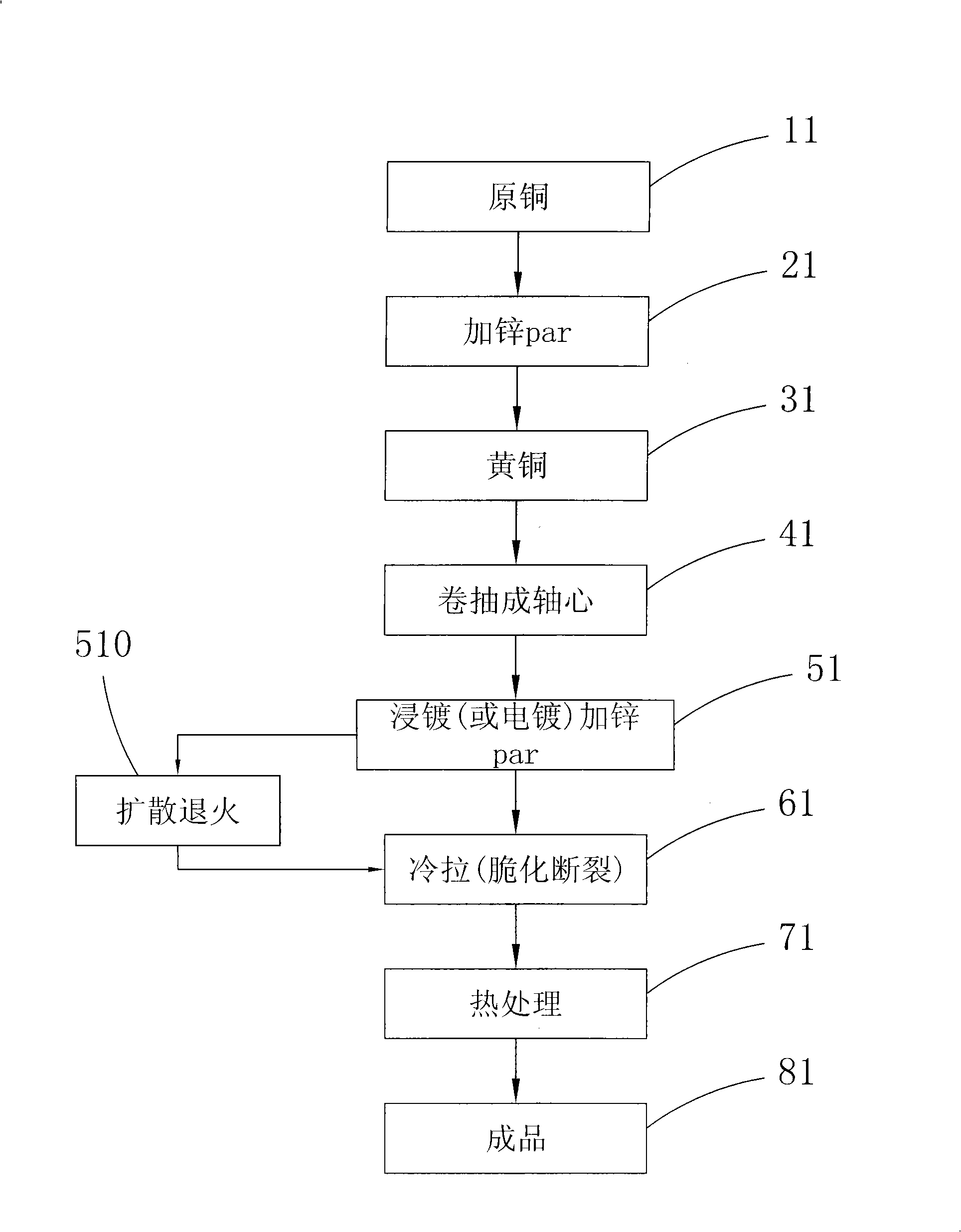
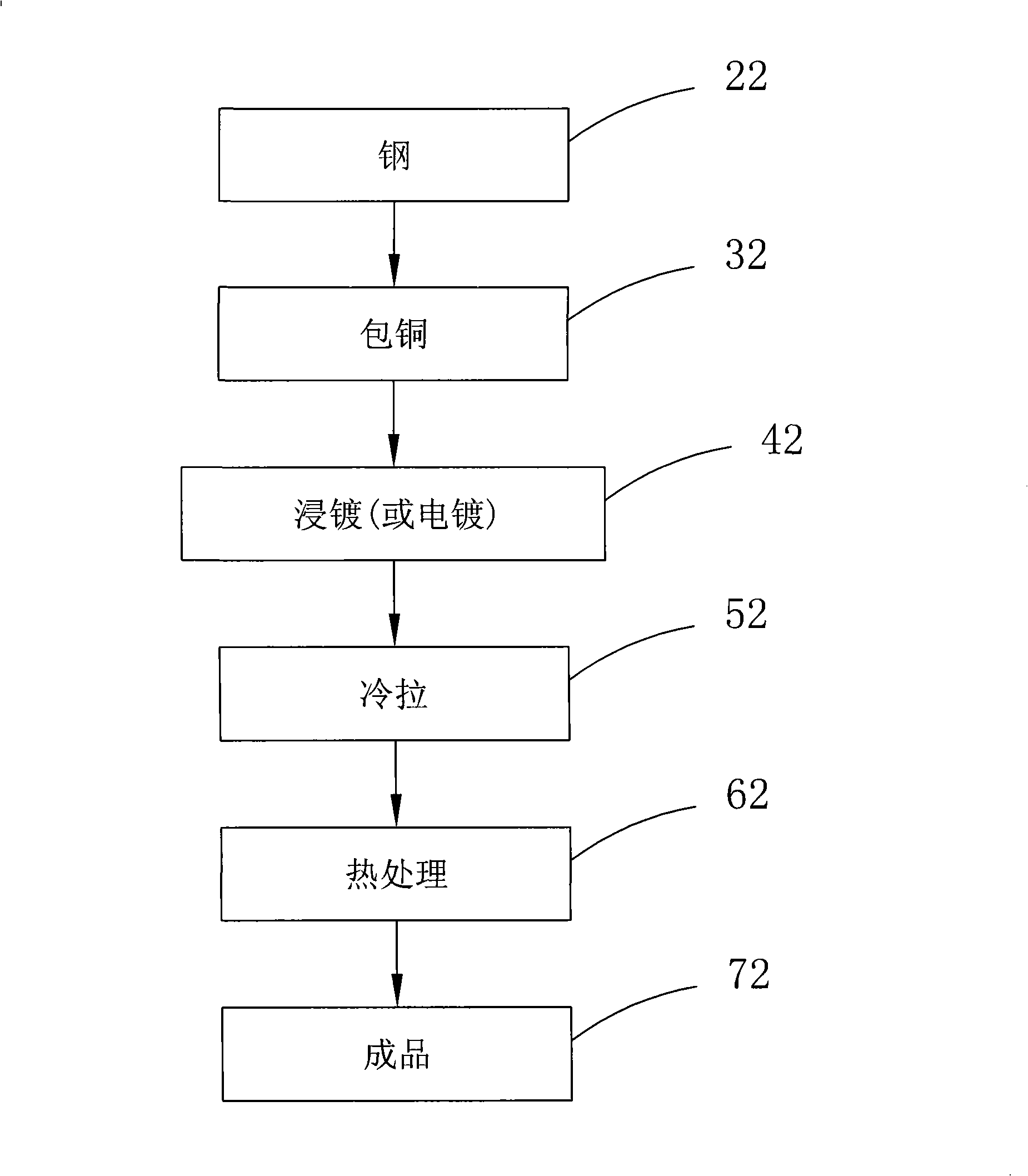
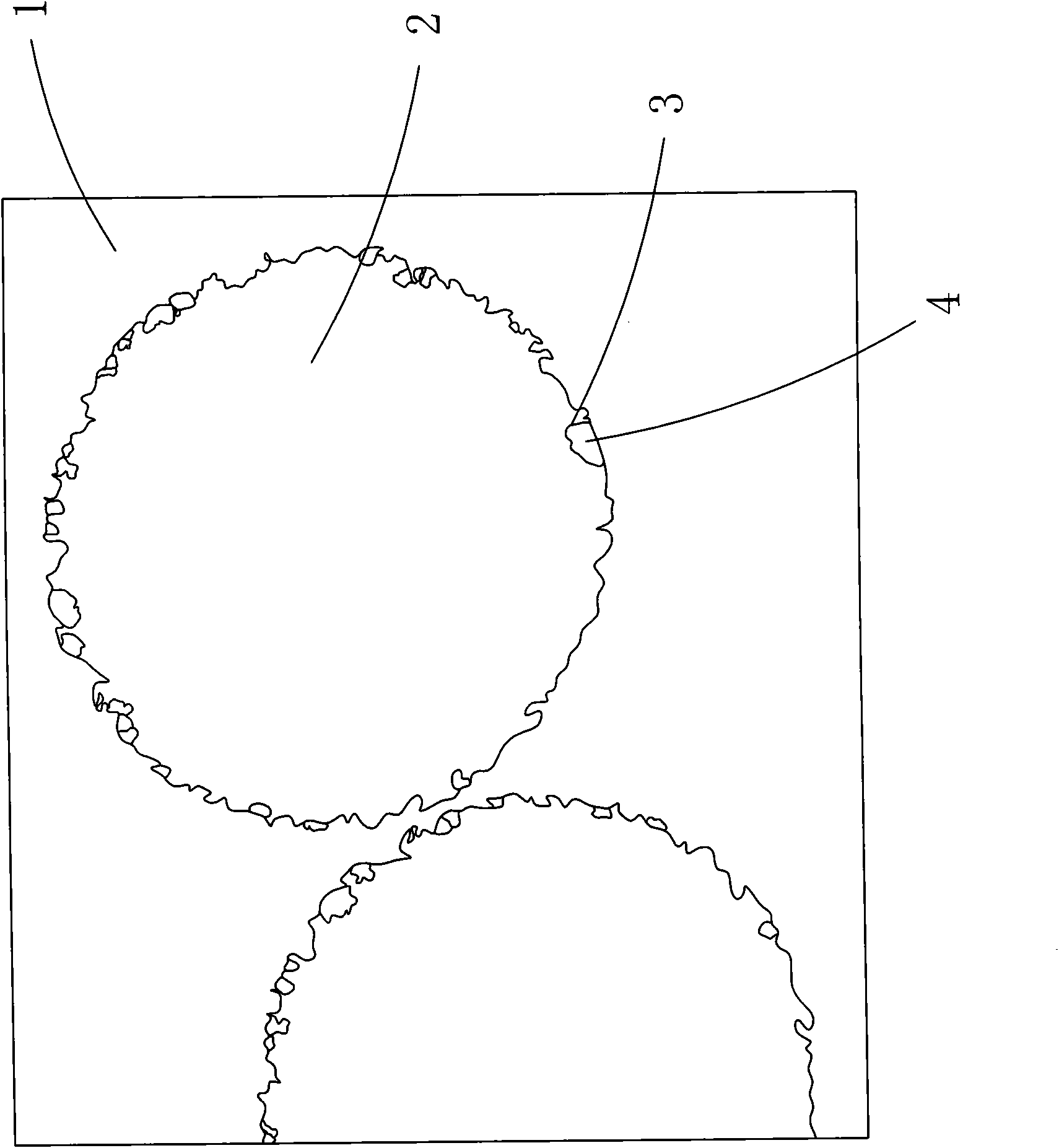
[0017] The present invention is a manufacturing method of electric discharge machine cutting wire. The main step is to form a metal alloy. The alloy can be made of brass or steel as the main core, and it can also be used in three parts such as pure copper, brass or copper-clad steel. Different materials directly form the core to form a relatively stable core of the processing line, and then electroplating or inclusion methods are used to form a β-phase brass cladding layer with a zinc content of about 5% to 45% of the specific gravity, while In order to make the EDM cutting wire cut more efficiently, γ-phase brass has a high composition of zinc, with an average specific gravity of about 65%. However, because the γ-phase alloy is extremely fragile, it is almost impossible to cold draw it. The γ-phase alloy material will break and recombine during cold drawing. Therefore, before cold drawing, the γ-phase coating is coated with a thinner layer of brass core by immersion plating or el


PUM


Abstract

The invention relates to a method for manufacturing a cutting line of an electrical discharge machine. The method mainly comprises the following steps that: two or more different metal alloys are combined to generate metal alloys with different phases by means of staged heat treatment; and fractured coating between different metals is generated after coating combination and cold drawing by means of different physical properties between the alloys so as to form the cutting line of the electrical discharge machine which can resist corrosion and has more effective cutting and further reduce production cost to form the more effective cutting line of the electrical discharge machine.

Description


Claims


Application Information

Patent Timeline
Owner 张国大
Why Eureka
Try Eureka