Boiler waste heat recovery device

A recovery device and boiler waste heat technology, applied in preheating, feed water heaters, fluid heaters, etc., can solve the problems of flue gas energy waste and achieve the effect of increasing the inlet water temperature

Inactive Publication Date: 2011-12-21
PENGLAI HUIYANG FOOD
View PDF5 Cites 5 Cited by
  • Summary
  • Abstract
  • Description
  • Claims
  • Application Information

AI Technical Summary

Benefits of technology

This technology helps recovering or reusing excessive amounts of wasted fuel from existing systems that use fossil fuels for power generation. It also increases the amount of steam produced by these new sources without increasing their own costs.

Problems solved by technology

This patented technical problem addressed by the present inventors relates to how efficiently recovering and reusing exhaust thermal power from conventional steam generators (STGs) without sacrificing their efficiency or performance.

Method used


Image

  • Boiler waste heat recovery device
  • Boiler waste heat recovery device

Examples


Embodiment Construction

[0016] The principles and features of the present invention are described below in conjunction with the accompanying drawings, and the examples given are only used to explain the present invention, and are not intended to limit the scope of the present invention.

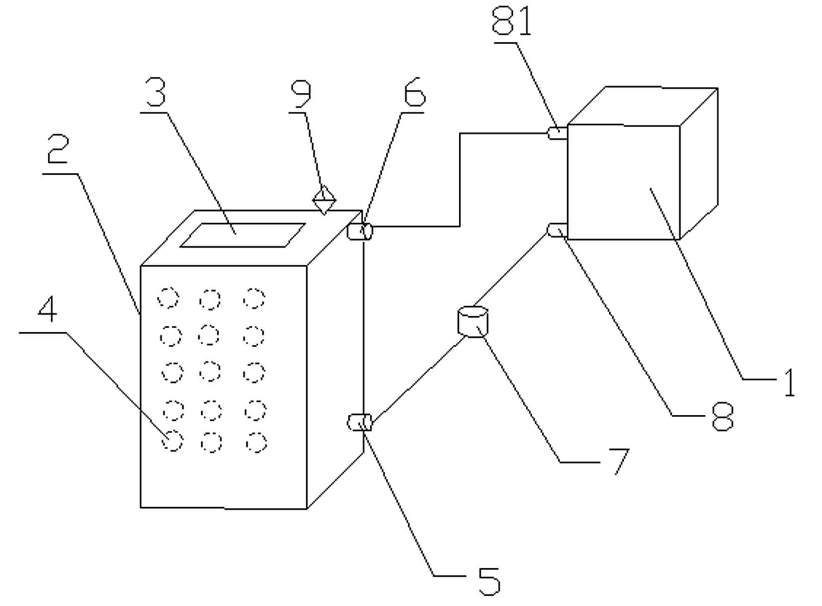
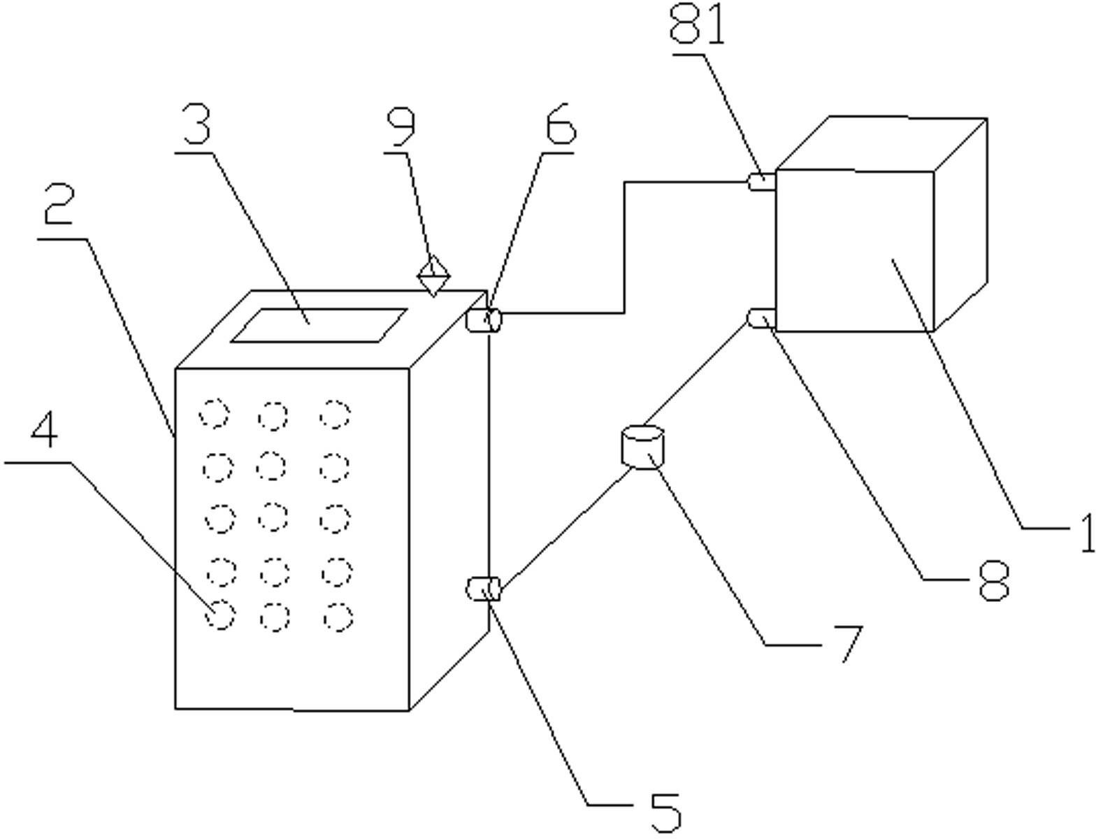
[0017] Such as figure 1 As shown, the boiler waste heat recovery device according to the embodiment of the present invention includes a boiler return tank 1 and a heat absorption tank 2 installed on the flue; the heat absorption tank 2 is provided with a There are a plurality of heat-absorbing steel pipes 4 inside the heat-absorbing tank 2, and a water inlet 5 and a water outlet 6 are arranged on the outer wall of the heat-absorbing tank 2, and the water inlet 5 and the water outlet 6 are respectively connected to the The boiler return water tanks 1 are connected.

[0018] The water inlet 5 is connected to a circulating water pump 7 through a pipeline, and the other end of the circulating water pump 7 is connected to


PUM


Abstract

The invention relates to a boiler waste heat recovery device, which comprises a boiler return water tank and a heat absorption tank installed on a flue. Among them, the heat absorbing tank is provided with a flue gas channel extending from the bottom of the heat absorbing tank to the top of the heat absorbing tank, a plurality of heat absorbing steel pipes are arranged inside the heat absorbing tank, and water inlets and outlets are provided on the outer wall of the heat absorbing tank. The water inlet and the water outlet are respectively connected to the boiler return water tank through pipes. The invention realizes secondary recovery and reuse of boiler waste heat, greatly increases boiler inlet water temperature, achieves the goals of coal saving, energy saving and environmental protection, and reduces cost while improving boiler thermal efficiency.

Description


Claims


Application Information

Patent Timeline
Owner PENGLAI HUIYANG FOOD
Why Eureka
Try Eureka