Sprue plugging device for casting sand mold at low pressure and method for casting sand mold at low pressure

A low-pressure casting and sand mold technology, applied in the field of aluminum alloy green sand mold low-pressure casting, can solve the problems of long solidification time, poor thermal conductivity, and low productivity of castings, and achieve the effects of reducing casting defects, filling molds smoothly, and improving production efficiency.

Inactive Publication Date: 2012-11-14
JINAN CASTING FORGING MACHINERY INST
View PDF5 Cites 8 Cited by
  • Summary
  • Abstract
  • Description
  • Claims
  • Application Information

AI Technical Summary

Benefits of technology

This technology helps prevent problems during high pressure gravity casting by allowing molten metal poured into small spaces between two parts without causing any issues like leakage or cracks on their surfaces when they come back up again after being cooled down too much before moving them towards the next step.

Problems solved by technology

The technical problem addressed by this patented technique for making castings quickly without losing their shape during high temperature processes such as sintered metal production or plasma display panels involves improving heat transfer between the molten material inside the tube walls while still maintaining stability through prevention of gravity effects on the filler fluid flow path.

Method used


Image

  • Sprue plugging device for casting sand mold at low pressure and method for casting sand mold at low pressure
  • Sprue plugging device for casting sand mold at low pressure and method for casting sand mold at low pressure
  • Sprue plugging device for casting sand mold at low pressure and method for casting sand mold at low pressure

Examples


Embodiment 1

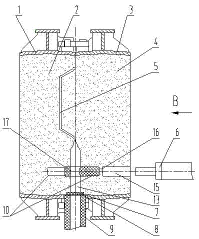
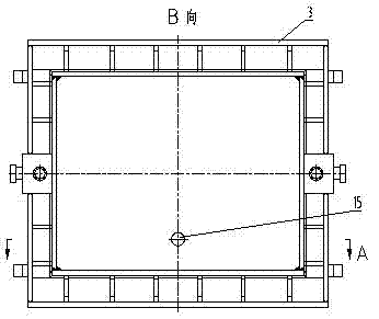
[0021] like Figure 1-5 Shown, a kind of sand mold low-pressure casting plugging gate device, it comprises upper sand mold 2 and lower sand mold 4, in the sprue position of described upper sand mold 2, lower sand mold 4, make the mold with casting draft angle Groove 10, in which the blocking member is placed, a guide hole 15 for the drive part of the blocking member drive mechanism to pass is provided on the back of the lower sand mold 4, and a guide hole 15 is provided outside the guide hole 15 Blocking drive mechanism. The driving mechanism of the blocking member includes an oil cylinder 6 , and the piston rod of the oil cylinder 6 faces the guide hole 15 of the lower sand mold 4 . Described plugging member comprises ceramic plugging block 17 and is arranged between guide hole 15 and sprue 13 and keeps guide hole 15 and sprue 13 apart retaining sand cluster 16, and the setting of retaining sand cluster 16 makes guide hole 15 and the sprue 13 cannot pass through; the groove 10

Embodiment 2

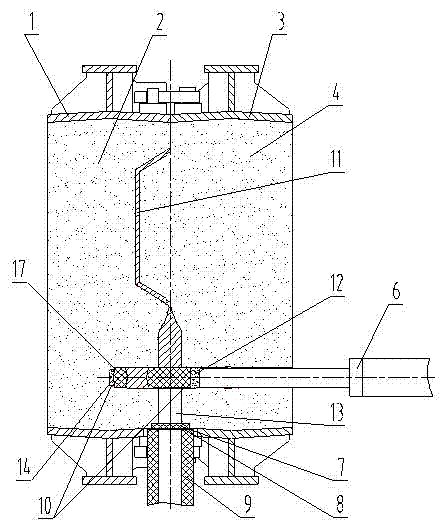
[0027] like Figure 6 ~ Figure 10 As shown, the similarities between this embodiment and the first embodiment will not be repeated. The difference is that the sealing member includes a resin sand block 19 fixed in the groove 10 and a sealing steel plate 20 slidingly fitted therewith. The resin sand block 19 is formed by bonding two halves of the sand block; a pouring hole is set on the resin sand block 19, and a guide groove 21 is arranged in the middle of the resin sand block 19 perpendicular to the axis of the pouring hole, and the guide grooves 21 are respectively arranged on the two halves of the sand block and combined to form a guide hole 18; the plugging steel plate 20 is set in the guide hole 18 on one side and is slipped with it to seal the pouring hole, and the other end of the plugging steel plate 20 extends into the guide hole 15. The guide holes 18 are distributed on both sides of the casting hole and are separated from the casting hole by 5-10mm of resin sand. The


PUM


Abstract

The invention discloses a sprue plugging device for casting a sand mold at low pressure and a method for casting the sand mold at low pressure. A groove is formed in a cast straight sprue part; a plugging piece is put into the groove; a square pouring hole is formed in the plugging piece; a plugging guide hole is formed in the back of a lower sand mold; an oil cylinder is arranged on the outer side of the guide hole; and a piston rod of the oil cylinder extends into the cast guide hole. The plugging method comprises the following steps that when a control system receives a signal indicating that the low-pressure casting is finished, the piston rod of the oil cylinder is controlled to quickly extend and pushes casting sand in a casting mold to forwards move together with the plugging piece along the guide hole; after reaching a certain travel, the oil cylinder stops moving, and the low-pressure casting pressurization system exhausts air and releases pressure; the plugging piece is staggered to separate a straight sprue; the plugged casting mold and a casting which is not completely solidified can move away from a pouring position, and the casting mold is overturned, cooled and solidified; and another casing mold is moved to the pouring position to be poured. The sprue plugging device is mainly used for manufacturing low-pressure cast complete equipment.

Description


Claims


Application Information

Patent Timeline
Owner JINAN CASTING FORGING MACHINERY INST
Why Eureka
Try Eureka